9
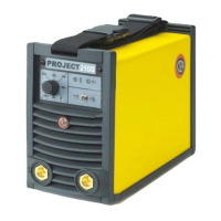
FIG. B
1 2 3
4
5
7
6
FIG. A
2000HB84
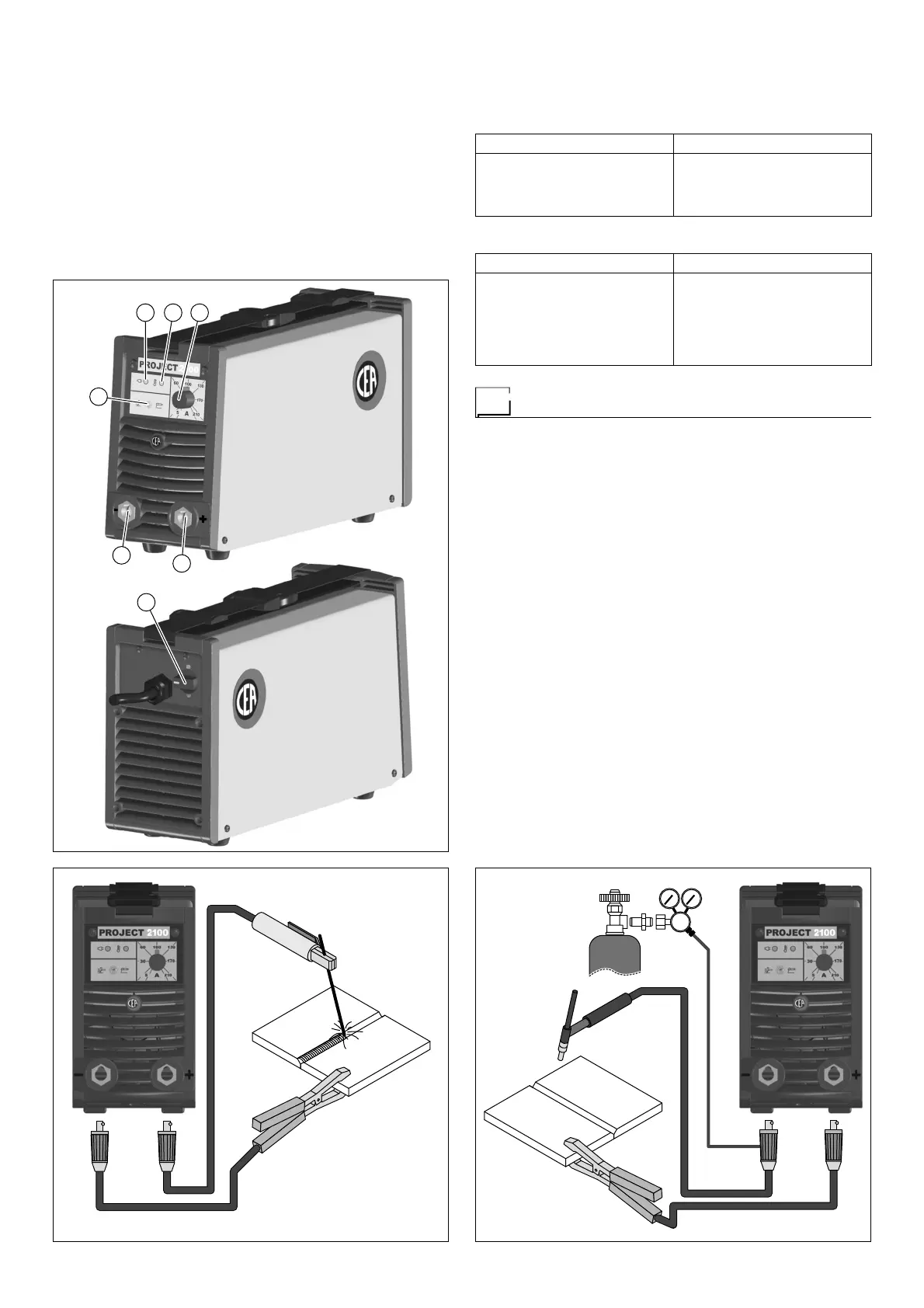
FIG. C
2000HB86
The current intensity to be used for the different types of wel ding,
within the field of regulation shown in table 4 is:
• High for plane, frontal plane and vertical upwards welding.
• Medium for overhead welding.
•
Low for vertical downwards welding and for joining small pre-
heated pieces.
A fairly approximate indication of the average current to use in the
welding of electrodes for ordinary steel is given by the fol lowing
formula:
I = 50 x (Øe - 1)
Where:
I = intensity of the welding current
Øe = electrode diameter
Example:
For electrode diameter 4 mm
I = 50 x (4 -1) = 50 x 3 = 150A
Table 3
WELDING THICKNESS (mm) Ø ELECTRODE (mm)
1,5 ÷ 3
3 ÷ 5
5 ÷ 12
12
2
2,5
3,2
4
Table 4
Ø ELECTRODE (mm) CURRENT (A)
1,6
2
2,5
3,2
4
5
30 ÷ 60
40 ÷ 75
60 ÷ 110
95 ÷ 140
140 ÷ 190
190 ÷ 210
TIG welding (Fig. C)
TIG welding melts the metal of the workpiece, using an arc struck
by a tungsten electrode.
The fusion bath and the electrode are protected by gas (Argon).
This type of welding is used to weld thin sheet metal or when el-
evated quality is required.
1) Connecting the welding cables:
•
Connect one end of the gas hose to the gas connecter on
the TIG torch and the other end to the Argon cylinder and
open it.
• With the machine switched off:
-
Connect the earth cable to the snap-on connector marked
+ (positive).
-
Connect the relative earth clamp to the workpiece or to the
workpiece support in an area free of rust, paint, grease,
etc..
-
Connect the TIG torch power cable to the snap-on con-
nector marked - (negative).
2) Adjust the welding current using the potentiometer (Pos. 3,
Fig. A).
3) Adjust the process switch (Pos. 6, Fig. A) to TIG (switch lever
moved to the left-hand side).
4) Start the welding machine by selecting pos. 1 on the line switch
(Pos. 7, Fig. A).
5) The white LED (Pos. 1, Fig. A) indicates that the welding ma-
chine is powered and ready to work.
6) Adjust the gas flow by manually turning the valve on the TIG
torch.