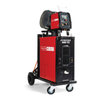
Do you have a question about the Cebora KINGSTAR 400 TS and is the answer not in the manual?
Explains the symbols and warnings on the machine's identification plate.
Details the meaning of various symbols and data on the machine's technical plate.
Provides instructions and warnings for safely installing the welding machine.
Describes how to properly connect the welding machine to the power supply.
Outlines safe procedures for lifting and transporting the welding equipment.
Covers the initial setup and first-time operation of the welding machine.
Details the physical assembly and connection of the power source and wire feeder.
Identifies and describes the components and connectors on the power source.
Identifies and describes the components and connectors on the wire feeder.
Explains the controls and indicators on the wire feeder's front panel.
Details the connectors located on the rear panel of the power source.
Describes the connection and function of the cooling unit interface.
Explains the touchscreen display and its primary functions.
Guides the user on how to navigate through the display menus and options.
Instructions for connecting the power source to the wire feeder.
How to choose appropriate welding parameters based on material and wire.
Explains different MIG welding processes like Pulse, Short, Root, SRS, 3D Pulse, Manual.
Describes different methods for starting the welding arc (2T, 4T, 3 Level, HSA, CRA, SPOT).
Details the settings for spot welding, including spot and pause times.
Explains the double level mode for adjusting wire speed and current.
Describes how to adjust key welding parameters like inductance and arc length.
Guides on selecting TIG DC welding processes (APC Lift, APC, XP).
Explains TIG start modes (2 stroke, 4 stroke, 3 level, 4 level).
Details arc striking methods, specifically Lift contact ignition.
Step-by-step guide for initiating the arc using the lift contact method.
Provides a table of adjustable parameters for TIG welding.
Explains the TIG Pulse function for thin sheets and parameter settings.
Describes the TIG DC APC process for maintaining constant heat input.
Details the TIG DC XP process with high-frequency pulses for better performance.
Explains the MMA DC welding process and initial setup.
Details adjustable parameters for MMA welding like Hot Start and Arc Force.
Covers saving, retrieving, and managing welding programs (JOBS).
Step-by-step guide to saving a welding JOB to memory.
Instructions on how to edit existing welding JOBs.
How to remove unwanted welding JOBs from memory.
Procedure for duplicating existing welding JOBs.
How to select and activate a saved JOB for welding.
Viewing detailed information about a saved JOB.
Enabling adjustments to parameters within a saved JOB.
Managing JOBs by backing them up to or loading them from a USB drive.
Accessing information on welding time, output, temperatures, and wire feed.
Accessing and managing various connected accessories for the power source.
Details on operating and managing the cooling unit.
Explains the setup and function of the welding mask T-LINK system.
Information on activating and using the Push-Pull Torch system.
Customizing the Push-Pull Torch operation.
Procedure for calibrating the Push-Pull Torch for optimal performance.
Adjusting the torque for the Push-Pull motor to ensure linear wire feed.
Calibrating the welding torch, likely for specific kits like SRS.
Setting a limit for wire emergence to prevent issues during startup.
Refers to a separate manual for Quality Control features.
Information on the gas regulation kit for MIG processes.
Explains the function of the input potentiometer for remote control.
Access point for configuring various machine settings.
Details a software option for production mode.
How to set the system clock and select the user interface language.
Manages user profiles (Normal, Expert, Administrator) and their permissions.
Operations for managing USB drives, including firmware updates and backups.
Configuring network settings for connecting the machine to a LAN.
Information on API REST interface for Industry 4.0 integration.
Procedures for resetting the machine to its original factory settings.
Setting a custom name for the power source and system.
Explains the icons and indicators shown on the main menu status bar.
Accessing information about the machine, distributor, and installing options.
Overview of the CEBORA KINGSTAR Welding System for automated welding.
Steps for configuring CANopen and enabling the robot interface.
Details DIP switch and terminal configurations for different interfaces.
Diagrams and identification of connectors on the rear panel.
Pinout and description for the CN1 connector.
Pinout and description for the CN2 connector, used for robot control.
Pinout and description for the CN3 connector, for optional control panels.
Pinout and description for the CN4 connector, for emergency signals.
Identifies the connection for the SRS Control accessory.
Identifies the connection from the power source-wire feeder.
Setting communication parameters for the robot interface.
| Input Voltage | 400V |
|---|---|
| Power Supply | Three-phase |
| Protection Class | IP23 |
| Welding Process | MMA, TIG |
| Welding Current Range | 400 A |
| Duty Cycle | 400A at 60% |