CEBORA S.p.A. 2
3.302.089 31/05/02
CONTENTS
1 - GENERAL INFORMATION..................................................................................................................3
1.1 - Introduction.......................................................................................................................................3
1.2 - General service policy........................................................................................................................3
1.3 - Safety information.............................................................................................................................3
1.4 - Electromagnetic compatibility............................................................................................................3
2 - SYSTEM DESCRIPTION ......................................................................................................................4
2.1 - Introduction.......................................................................................................................................4
2.2 - Technical specifications.....................................................................................................................4
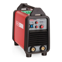
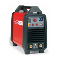
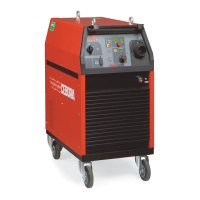
2.3 - Description of power source art. 296..................................................................................................4
3 - MAINTENANCE...................................................................................................................................6
3.1 - Periodic inspection, cleaning..............................................................................................................6
3.2 - Sequence of operations (fig. 3.2.1).....................................................................................................6
3.2.1 - Power source commands and signals..................................................................................................6
3.2.2 - Power source operation......................................................................................................................7
3.3 - Troubleshooting. ...............................................................................................................................9
3.3.1 - The power source does not start, control panel off. .............................................................................9
3.3.2 - Power source powered, control panel on, fan (15) stopped................................................................11
3.3.3 - Power source powered, the indicators show no correct values...........................................................11
3.3.4 - The start button produces no effect...................................................................................................12
3.3.5 - No gas flows from the torch.............................................................................................................13
3.3.6 - Gas flows from the torch, the pilot arc does not light (high frequency missing).................................14
3.3.7 - Gas flows from the torch, the pilot arc does not light (nozzle voltage missing)..................................16
3.3.8 - Irregular pilot arc starts, unstable pilot arc........................................................................................17
3.3.9 - Transfer arc does not take place or is too weak for cutting. ...............................................................18
3.4 - Alarm signals. .................................................................................................................................19
3.4.1 - Yellow (G) and red (N) leds lit = temperature outside limits.............................................................19
3.4.2 - Red leds (L) and (N) lit = low gas pressure.......................................................................................19
3.4.3 - Red led (N) lit = power source blocked. ...........................................................................................20
3.4.4 - Alarms shown at power source start-up............................................................................................20
3.4.5 - Alarms shown during pilot arc or transfer arc (cutting) operation......................................................21
4 - COMPONENTS LIST ..........................................................................................................................22
4.1 - Power source art. 296 : see file ESP296.pdf enclosed at the end of the manual..................................22
4.2 - Components table : see file ESP296.pdf enclosed at the end of the manual. ......................................22
4.3 - Spare parts list.................................................................................................................................22
5 - ELECTRICAL DIAGRAMS.................................................................................................................23
5.1 - Power source art. 296 : see file SCHE296.pdf enclosed at the end of the manual...............................23
5.2 - Waveforms......................................................................................................................................23
5.2.1 - Open circuit nozzle voltage, interrupted after approximately 300 msec., for missing pilot arc current
(par. 3.3.6, 3.3.7, 3.3.8). ..................................................................................................................23
5.2.2 - HF board (22) power supply voltage, interrupted after approximately 300 msec., for missing pilot arc
current (par. 3.3.6)...........................................................................................................................23
5.2.3 - Command signal for HF board (22), interrupted after approximately 300 msec., for missing pilot arc
current (par. 3.3.6)...........................................................................................................................23
5.3 - Filter board (36) code 5.602.078. .....................................................................................................24
5.4 - Power board (35) code 5.602.140/A.................................................................................................24
5.5 - Panel board (31) code 5.602.124......................................................................................................26
5.6 - HF board (22) code 5.602.074/C......................................................................................................27
 Loading...