Do you have a question about the Cebora PLASMA PROF 80 and is the answer not in the manual?
Purpose of the manual to train maintenance personnel for plasma cutting systems.
Responsibility of customer/operator for equipment use, maintenance, and qualified personnel for repairs.
Safety notes are integral; disconnect power before access; use precautions for hazardous potentials.
Instructions for electromagnetic compatibility are in the Instruction Manual.
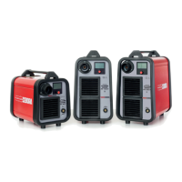
Overview of the PLASMA PROF 80 system for cutting conductive materials.
Technical specifications are found on the machine plate, Instruction Manual, and Sales Catalogue.
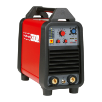
Detailed description of the art. 947 power source, its components, and operation.
Procedures for periodic removal of dirt and dust, checking terminals and connections.
Sequence reflecting correct machine operation for troubleshooting guidance.
Identification of commands and signals on the power source front panel.
Step-by-step procedure for operating the power source, including checks and tests.
Troubleshooting steps for when the power source fails to start and the status LED is off.
Troubleshooting steps for when the power source is powered but the fan is stopped.
Troubleshooting steps when the start button does not initiate any operation.
Troubleshooting steps for when no gas is dispensed from the torch.
Troubleshooting steps when gas flows but the pilot arc fails due to missing high frequency.
Troubleshooting steps when gas flows but the pilot arc fails due to missing nozzle voltage.
Troubleshooting steps for when the output voltage is irregular during open circuit operation.
Troubleshooting steps for unstable or irregular pilot arc initiation.
Troubleshooting steps when transfer arc fails or is too weak for cutting.
Indicates transformer temperature is outside allowed limits, with recommended actions.
Indicates gas pressure at the intake has fallen below allowed limits.
Alarm indicating start button pressed during power source startup sequence.
Alarm indicating the central adapter protection is missing or not activated.
Alarm indicating reed contact is closed upon power source startup, blocking operation.
Reference to ESP947.pdf file for power source art. 947 details.
Reference to ESP947.pdf file for components table.
Lists essential and recommended spare parts with their codes and descriptions.
Reference to SCHE947.pdf file for electrical diagrams.
Displays various signal waveforms for system analysis.
Topographical drawing and connector/fuse table for the fuse board.
Topographical drawing and connector table for the relay board.
Topographical drawing, connector table, and fuse table for the power board.
Topographical drawing and connector table for the setting board.
Topographical drawing and connector table for the control board.
Topographical drawing and connector table for the HF board.
Topographical drawing and connector table for the HF-filter board.
| Input Voltage | 400 V |
|---|---|
| Input Current | 16 A |
| Output Current | 20 - 80 A |
| Cutting Capacity | 25 mm |
| Protection Class | IP23 |
| Frequency | 50/60 Hz |
| Cooling System | Air |
| Duty Cycle | 60% |