CEBORA S.p.A. 20
3.4
- Alarm signals.
3.4.1 - Led (G) lit = transformer (50) temperature outside limits.
This alarm indicates that the temperature of the transformer (50) has risen beyond the allowed
limits. We recommend not to shut off the power source, to keep the fan (45) running and thus
allow rapid cooling.
This is reset automatically when the temperature returns within the allowed limits.
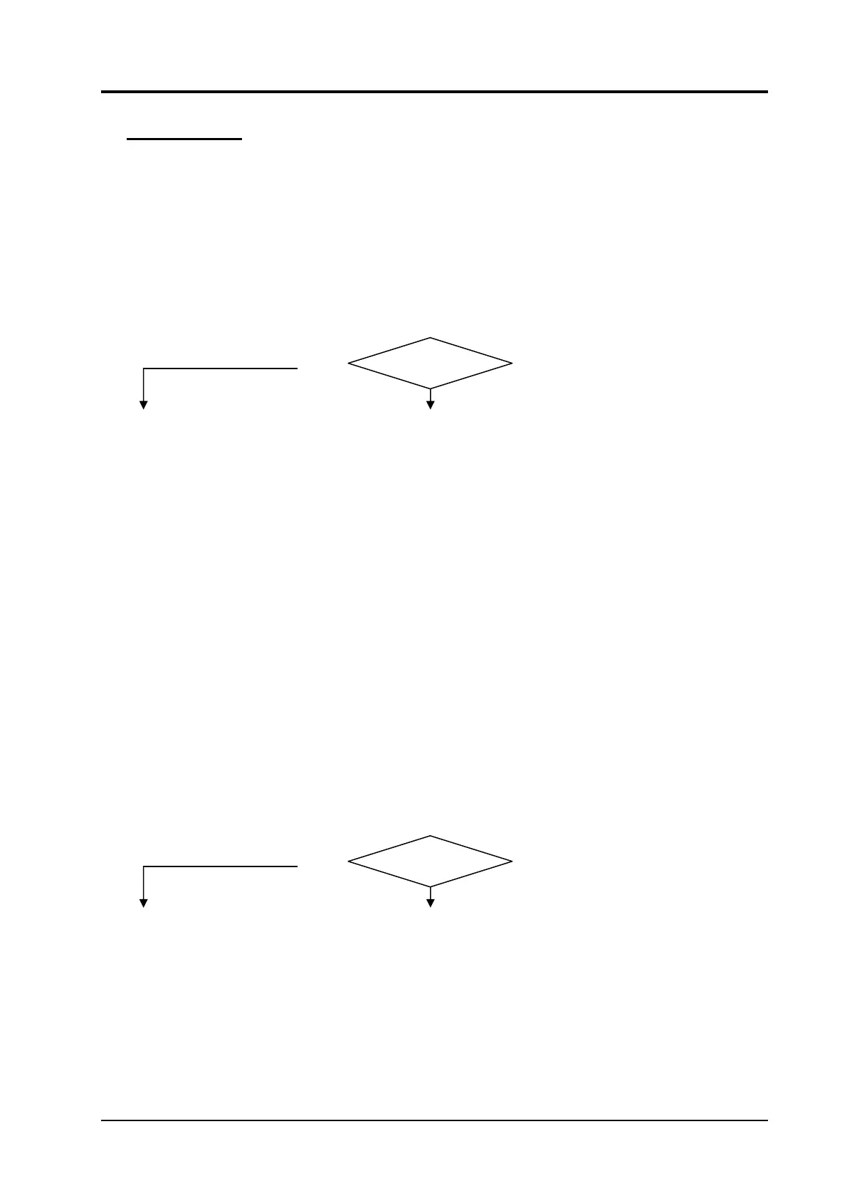
THERMOSTAT ON THE TRANSFORMER (50) TEST.
Correct?
Control board (9), connector J3, terminals 3 and 4 = 0 Vac (contact closed), with transformer
(50) at ambient temperature; 27 Vac, contact open, with temperature beyond limits.
YES
NO
♦ Check the wiring between the thermostat on transformer (50) and terminals 3 and
4 of J3 on control board (9).
♦ Make sure the thermostat on the winding of the central column of the transformer
(50) is intact and correctly positioned.
♦ If the alarm occurs while cutting, and the transformer (50) is evenly heated, make
sure that the usage cycle is not greater than indicated in the power source
specifications.
♦ If the alarm occurs while cutting, and only some windings of the transformer (50)
are heated, the transformer (50) may be partially short-circuited and thus need to
be replaced.
♦ Replace thermostat.
♦ Replace control board (9).
3.4.2 - Led (L) steadily lit = low gas pressure.
This alarm indicates that the gas pressure at the power source intake (B) has fallen below the
allowed limits (approximately 3 bar).
This is automatically reset when the pressure returns within the allowed limits.
PRESSURE SWITCH (35) TEST.
Correct?
Control board (9), connector J3, terminals 1 - 2 = 0 Vac, contact closed, with pressure correct;
27 Vac, contact open, pressure low.
YES
NO
♦ Check the wiring between control board (9) and pressure switch (35).
♦ Check for the presence of gas at the intake fitting (B) and make sure the pressure
and flow rate in the intake line meet specifications (see Instruction Manual).
♦ Make sure that the pressure regulator (E) and pressure gauge (F) are working
properly.
♦ Make sure that the threaded part of the air fitting (B) inserted in the pressure
regulator (E) is no more than 6 - 8 mm (1/4” - 5/16”) long, to avoid any possible
malfunction of the regulator (E).
♦ Make sure there are no occlusions in the gas hoses of the power source.
♦ Replace the pressure switch (35).
3.302.167 25/06/04