Do you have a question about the Cebora PLASMA PROF 123 ACC and is the answer not in the manual?
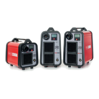
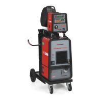
The CEBORA PLASMA PROF 123 ACC is a cutting system designed for plasma arc cutting of electro-conducting materials. It comprises an electronic Power Source (art. 956) and a set of torches and accessories for manual applications. The Power Source is controlled by microprocessor-based circuits that manage the cutting system's operative functions and the operator interface.
The PLASMA PROF 123 ACC is a direct voltage, current-controlled Power Source consisting of a three-phase bridge rectifier and an IGBT DC/DC converter. The system's core functionality revolves around generating a plasma arc for cutting.
The switch (49) powers the service transformer (53), which in turn feeds the electronic boards and internal services via the fuse board (53). The power transformer (37) has a primary circuit with six windings, allowing the Power Source to operate at 230, 400, or 440 Vac 50/60 Hz, depending on the voltage changer setting. The service transformer (53) voltage changer is set near the main voltage changer.
The transformer (37) is energized through contactor (2), which is controlled by the control board (47) after the DC-capacitor (20) pre-charge and transformer (37) pre-magnetization phases are complete. One of the transformer (37) primary windings supplies 230 Vac to power the fan (23) for cooling the Power Source's power elements.
The measure board (57) monitors the mains voltage signal from the secondary circuit of transformer (37), detecting the presence and amplitude of the three-phase supply voltage. Incorrect values trigger an error signal to the control board (47).
The rectifier bridge (34), connected to the transformer (37) secondary circuit, supplies the capacitor (20) and the power board (56). The power board (56) contains the IGBT module and two Hall effect current transducers to measure the Power Source and pilot arc output currents. The IGBT module includes the switching element, the IGBT, and a freewheeling diode configured in a "chopper" layout.
At the negative output (1) of the IGBT module on the power board (56), the choke (35) is connected to level the arc current. The HF transformer (50) is also connected at the output for the electrode potential, on the central adapter (41) for the cutting torch. Terminal TP1 of the power board (56) corresponds to the positive output (3) of the IGBT module and represents the ground potential output for workpiece connection. A Hall effect current transducer on the power board (56) sends the Power Source output current signal to the control board (47).
Terminal J1 of the power board (56) also corresponds to the positive output (3) of the IGBT module and represents the nozzle potential output. The nozzle resistor (33), which aids pilot arc operation, is connected to it. Another Hall effect current transducer on the power board (56) sends the pilot arc current signal to the control board (47).
The system current is adjusted by the control board (47), which generates the IGBT drive signal (waveform/duty cycle) by comparing the current reference signal from the control board (47) with the current feedback signal from the transducers on the power board (56). These transducer signals are also used for switching between the pilot arc and transfer arc. Specifically, when the Power Source output current (TP1 transducer signal) equals the pilot arc current (J1 transducer signal), the control drives pilot arc operation by closing the nozzle contactor (55). When the Power Source output current exceeds the pilot arc current, the control drives transfer arc operation (cutting) and opens the nozzle contactor (55).
The fuse board (53) houses fuses for the electronic boards and Power Source internal services (contactors and solenoid valves). The supply board (51), powered by the fuse board (53), generates the control board (47) power voltage. A control circuit on the supply board (51) generates an error signal if its input voltage drops by 30% below the rated value, stopping the Power Source and displaying error code 99 "OFF" on the operator panel.
The pre-charge board (3), controlled by the control board (47), commands the power transformer (37) pre-magnetization via resistors R16, R17, R18 and relay RL3.
The control board (47) contains the main microprocessor, managing other specialized boards, processing the driver signal for the IGBT module on the power board (56), commanding the line contactor (2) and nozzle contactor (55), managing plasma gas control devices (solenoid valves and pressure detector), and performing system diagnostics. It also manages the operator interface, which includes two displays (U and V) for torch type, error codes, cutting current, and nozzle hole diameter, a knob (Z) for setting cutting current, LEDs for operating status, and a button (W) for function selection. An RS232 communication port (BD1) on the control board (47) allows firmware updates via a PC.
The control board (47) receives temperature signals from thermostats on the transformer (37) and the IGBT module dissipater on the power board (56). Over-temperature signals stop the Power Source and display the corresponding error code.
The sensor board (52) acts as an interface, receiving and conditioning disturbed signals from critical system areas, including HF board (27) command, Power Source output voltage, and pilot arc voltage. The Power Source output voltage signal, filtered and converted to a PWM signal by the HF-filter board (32) and sensor board (52), is sent to the control board (47) to check cutting conditions.
The HF board (27), with the HF transformer (50), generates high voltage and high frequency pulses for the torch electrode and nozzle, initiating the pilot arc. Its operation depends on the Power Source output voltage between the positive pole (nozzle potential) and the common point between choke (35) and HF transformer (50) (electrode potential). Above 200 Vdc, it generates pulses; below this, it stops.
The pilot arc has a maximum length of 2.5 seconds. If cutting doesn't start within this time, the pilot arc halts until the next start command. The HF-filter board (32) is crucial for preventing HF pulses from damaging the Power Source.
| Brand | Cebora |
|---|---|
| Model | PLASMA PROF 123 ACC |
| Category | Welding System |
| Language | English |