CEBORA S.p.A. 2
3.302.269 12/04/2012
CONTENTS
1
- GENERAL INFORMATION. .............................. 3
1.1 - Introduction. .................................................... 3
1.2 - General service policy..................................... 3
1.3 - Safety information........................................... 3
1.4 - Electromagnetic compatibility......................... 3
2 - SYSTEM DESCRIPTION.................................... 4
2.1 - Introduction. .................................................... 4
2.2 - Technical specifications. ................................. 4
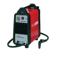
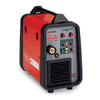
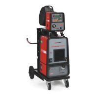
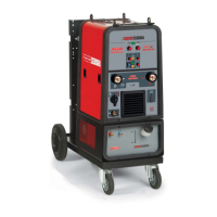
2.3 - Power Source art. 956...................................... 4
3 - MAINTENANCE. ................................................ 7
3.1 - Periodic inspection, cleaning........................... 7
3.2 - Operative sequence.......................................... 7
3.2.1 - Power Source controls and signals............. 7
3.2.2 - Power Source operation............................. 8
3.3 - Troubleshooting............................................. 10
3.3.1 - The Power Source does not start, operator
panel off. ................................................. 10
3.3.2 - Power Source powered, operator panel on,
fan (23) stopped....................................... 13
3.3.3 - Power Source powered, display and
signalling do not show the correct values.14
3.3.4 - The start command produces no effect.... 15
3.3.5 - No gas flows from the torch..................... 16
3.3.6 - Gas flows from the torch, pilot arc does not
start (no nozzle voltage). ......................... 17
3.3.7 - Gas flows from the torch, pilot arc does not
start (no high frequency). ........................ 18
3.3.8 - In open circuit operation, the output voltage
is not regular............................................ 20
3.3.9 - Irregular pilot arc striking, unstable pilot
arc............................................................ 22
3.3.10 - There is no transfer arc or it is too weak to
perform cutting........................................ 24
3.4 - Error codes and alarm signals........................ 26
3.4.1 - 02 - Hardware lockup. ............................. 26
3.4.2 - 30 - Minimum current signal error from
power board (56) (current transducer
offset). ..................................................... 26
3.4.3 - 35 - No current at power board (56) output.
................................................................. 26
3.4.4 - 39 - Nozzle current transducer reading error
(current transducer offset). ...................... 26
3.4.5 - 40 - Dangerous voltage............................ 27
3.4.6 - 49 - Nozzle current during cutting........... 28
3.4.7 - 50 - Torch central adapter protection not
inserted.................................................... 28
3.4.8 - 51 - Torch recognition failed. .................. 28
3.4.9
- 53 - “trG” on displays (U). Start button
pressed at start-up or during operating
mode reset................................................29
3.4.10 - 55 - Exhausted electrode..........................29
3.4.11 - 67 - Mains voltage does not meet
specifications. ..........................................30
3.4.12 - 73 - “TH””0” on displays (U) (V).
Transformer (37) high temperature..........31
3.4.13 - 74 - “TH””1” on displays (U) (V). Power
board (56) igbt group high temperature...31
3.4.14 - 78 - “GAS”“LO” on displays (U) (V). Gas
low pressure.............................................32
3.4.15 - 99 - “OFF” on display (U). Incorrect mains
voltage (machine shutdown)....................32
4 - COMPONENTS LIST.........................................33
4.1 - Plasma PROF 123 ACC : see file ESP956.pdf
enclosed at the end of the manual..................33
4.2 - Components table: see file ESP956.pdf
enclosed at the end of the manual..................33
5 - ELECTRICAL DIAGRAMS. .............................33
5.1 - Plasma PROF 123 ACC : see file SCHE956.pdf
enclosed at the end of the manual..................33
5.2 - Waveforms.....................................................33
5.2.1 - Power Source output voltage (par. 3.3.6,
3.3.8)........................................................33
5.2.2 - Nozzle output voltage (par. 3.3.6, 3.3.7,
3.3.9)........................................................33
5.2.3 - HF board (27) input voltage = pilot arc
voltage (par. 3.3.7, 3.4.10).......................34
5.2.4 - Pilot arc current reference signal (par.
3.3.8)........................................................34
5.2.5 - Power Source output current feedback
signal (par. 3.3.8).....................................34
5.2.6 - Nozzle current feedback signal (par.
3.3.10)......................................................34
5.3 - Fuse board (53), code 5.602.403....................35
5.4 - Pre-charge board (3), code 5.602.415............36
5.5 - Measure board (57), code 5.602.388..............37
5.6 - Supply board (51), code 5.602.299/D............38
5.7 - Control board (47), code 5.602.398/A...........39
5.8 - Power board (56), code 5.602.401.................41
5.9 - Driver board (56), code 5.602.396.................42
5.10 - Sensor board (52), code 5.602.416. ...............42
5.11 - HF board (27), code 5.602.034/B. .................43
5.12 - HF-filter board (32), code 5.602.376. ............43