3.3.3 - In open circuit operation, the output voltage is not regular.
OPEN CIRCUIT OUTPUT VOLTAGE TEST IN MANUAL MODE.
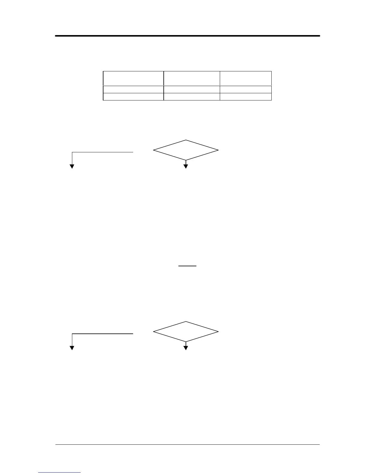
Potentiometer (3)
position
Output voltage
Vac
Waveform
at minimum 2 Fig. 5.2.2
at maximum 7 Fig. 5.2.3
q Switch (1) in manual mode (lever to the right), power source output terminals = voltage
values and waveforms as in the table, with start button pressed.
q Holding down the start button, turn the potentiometer (3) and make sure the line of the output
voltage waveform changes in a linear, non-abrupt fashion, between the minimum and
maximum values of fig. 5.2.2 and 5.2.3.
YES
NO
♦ Check the wiring between CN4 control board (27) and static switch (14).
♦ Check the wiring between the switch (1) and connector CN3 on board (27):
CN3, terminals 1 and 2 = 0 ohm (contact closed), terminals 3 and 4 = > kohm
(contact open) = manual mode. If incorrect, check the status of the switch (1) and
replace if defective.
♦ Check the connections between the secondary transformer circuit (26) and output
terminals of the power source. If you find loose or burnt connections, clean
thoroughly and tighten, or replace any damaged terminals or components.
♦ Replace static switch (14).
♦ Replace control board (27).
NOTE
Timed operation is not possible in the following test, as timing begins only when the output
current exceeds approximately 100 Aac.
OPEN CIRCUIT OUTPUT VOLTAGE TEST IN AUTOMATIC MODE.
q Switch (1) in automatic mode (lever to the left), power source output terminals = 7 Vac and
waveform per fig. 5.2.3, with start button pressed, regardless of the position of the
potentiometers (2) and (3) and the switch (11).
YES
NO
♦ Check the wiring between CN4 control board (27) and static switch (14).
♦ Check the wiring between the switch (1) and connector CN3 on board (27):
CN3, terminals 1 and 2 = > kohm (contact open), terminals 3 and 4 = 0 ohm
(contact closed) = automatic mode. If incorrect, check the status of the switch (1)
and replace if defective.
♦ Check the connections between the secondary transformer circuit (26) and output
terminals of the power source. If you find loose or burnt connections, clean
thoroughly and tighten, or replace any damaged terminals or components.
♦ Replace static switch (14).
♦ Replace control board (27).
♦ Correct operation.