31
Conrmationenablesaccesstothefollowingweldingpa-
rameters:
• HOT-START CURRENT adjustable from 0 to 100% of
the welding current (with saturation at maximum current).
Percentage of current added to the welding current to en-
ablearcignition.Theparameteractivatesinred.Conrm
andadjusttheparameter.Conrmationenablesautomat-
ic passage to the next parameter, or turn knob B to select
the desired parameter.
• HOT-START TIME adjustable from 0 to 500 ms.
• ARC FORCE adjustable from 0 al 100%. (with saturation
at maximum current). This overcurrent facilitates transfer
of melt metal.
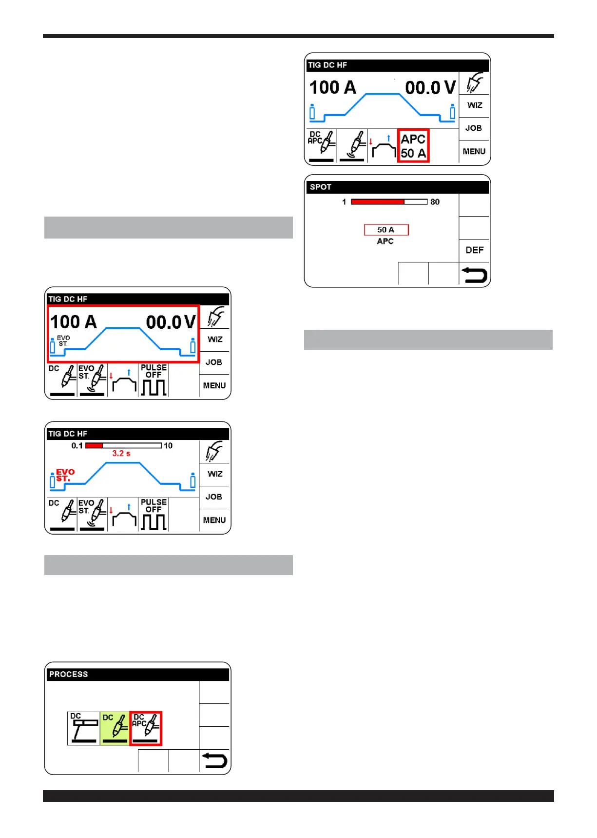
14. EVO ST. ADJUSTMENT
When an “EVO ST” ignition is set, an icon appears on the
currentcontrol-owgraphthatcanbeselectedbymeans
of knob B.
Select and
conrm the
EVO ST pa-
rameter.
Set the du-
ration and
conrm
15. TIG DC APC (ACTIV POWER CONTROL)
This function acts so that when the arc length is short-
ened, the current increases, and vice versa; the operator
then controls the heat gain and penetration just by mov-
ing the welding torch.
The amplitude of variation of current per unit of voltage is
adjustable by means of the APC parameter
Select and
conrmAPC
welding pro-
cess.
(see chapter
5)
Select and
conrmAPC
current ad-
j u s t m e n t
APC
Set and con-
rm ampli-
tude of vari-
ation of the
current.
To return to the main screen, press knob B (do not re-
lease immediately) (> 0.7 sec.)
16 TIG DC
This welding machine is suitable for welding using the
TIG procedure: stainless steel, iron, and copper.
Connect the ground cable connector to the positive pole
(+) of the welding machine, and the terminal to the work-
piece as close as possible to the welding point, making
sure there is good electrical contact.
• Connect the power connector of the TIG torch to the
negative pole (-) of the welding machine.
• Connect the torch connector to connector F of the
welding machine.
•ConnectthettingofthetorchgashosetotheE ma-
chine connector and the gas hose coming from the cyl-
inderpressureregulatortothegasttingH.
• Turn on the machine.
• Set the welding parameters as described in chapter 4.2
• Do not touch live electrical parts and output terminals
when the machine is powered.
•Theinertgasowmustbesetatavalue(literspermin-
ute) approximately 6 times the electrode diameter.
• If gas-lens type accessories are used, the gas delivery
must be reduced by approximately 3 times the electrode
diameter.
• The ceramic nozzle diameter must be between 4 and 6
times the electrode diameter.
Normally, the gas most frequently used is ARGON be-
cause it costs less than the other inert gases. However,
ARGON mixtures can also be used, with max. 2% HY-
DROGEN for welding stainless steel and HELIUM or AR-
GON-HELIUM mixtures for welding copper.
These mixtures increase the heat of the arc while weld-
ing, but they are also much more costly. If HELIUM gas
is used, increase the liters per minute up to 10 times the
diameter of the electrode (e.g. diameter 1.6 x10= 16 lt/min
of Helium). Use D.I.N. 10 protective glass until 75A and
D.I.N. 11 from 75A on.




 To Next Page