This document is an instruction manual for a MIG welder, specifically the "Panther 180" model.
Function Description:
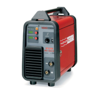
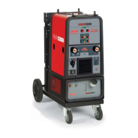
The Panther 180 is a MIG (Metal Inert Gas) welder designed for welding soft steel, stainless steel, and aluminum. It operates as a single-phase transformer-rectifier. The machine allows for continuous electrode welding and features controls for adjusting welding voltage range, wire speed, spot welding duration, and rest time between spot welds. It is equipped with a thermostat for protection against overheating, which, when tripped, stops welding operations and illuminates a yellow LED while the fan continues to run.
Important Technical Specifications:
The welder is manufactured according to international standards EN 50199 and EN 60974.1.
- Input Voltage (U1): 1~ 50Hz, 240V (as indicated on the nameplate).
- Rated Supply Current (I1 max.): 21.5A (as indicated on the nameplate).
- Effective Input Current (I1 eff.): This value is the maximum effective input current, considering the duty cycle.
- Welding Current (I2 MAX.): 180A.
- Secondary Open-Circuit Voltage (U0): 20.5V.
- Secondary Voltage with Welding Current (U2): 17.7V at 60% duty cycle, 17V at 100% duty cycle.
- Duty Cycle (X): 20% at 180A/20.5V, 60% at 130A/17.7V, 100% at 110A/17V. The duty cycle expresses the percentage of a 10-minute period during which the machine can run at a certain current without overheating.
- Protection Rating (IP21): Grade 1 for the second digit indicates suitability for outdoor use in rain. The machine is also suitable for use in high-risk environments and environments with a pollution rating of 3.
- Gas Type: Uses inert gases such as CO2, ARGON, or a mixture of ARGON + CO2 for protection.
- Noise Levels: The power source alone does not produce noise levels exceeding 80 dB. However, the welding procedure itself may produce noise levels in excess of 80 dB, requiring the operator to take necessary safety precautions.
Usage Features:
- Installation: Requires placement in an adequately ventilated, dust-free area, maintaining at least 500 mm of free space around the machine to prevent overheating. Filtering devices over air intake points are not permitted. Connections must comply with current regulations and safety laws. The power cable must be connected to a mains supply matching the welder's voltage, either permanently with a main switch or via a plug-socket connection. The yellow-green wire must be connected to the earth terminal, and the earth clamp (20) to the workpiece.
- Controls:
- Switch (A): Turns the machine on/off and regulates the welding voltage range.
- Setting Knob (B): Adjusts welding wire speed.
- Yellow LED (D): Lights when the thermostat is tripped due to overheating.
- Green LED (E): Indicates the machine is turned on.
- Welding Torch Connector (F): For connecting the welding torch.
- Spot Time Adjuster Knob (G): Sets the duration of spot welding. Pressing the gun button starts welding for the set time.
- Rest Time Adjusting Knob (H): Adjusts the rest time between spot welds, active only when spot time is enabled.
- Welding Mild Steel: Uses 75% ARGON + 25% CO2 or 100% CO2. Welding current is selected via a rotary switch (40). Wire speed is adjusted with the potentiometer knob (B) to achieve a constant, continuous welding noise.
- Welding Aluminum: Requires 100% ARGON as protection gas and specific wire compositions (e.g., 3-5% silicon wire for ALLUMAN/ANTICORODAL, 5% magnesium wire for PERALUMAN/ERGAL). Abrasive grinders and tool brushes designed for aluminum must be used. Cleanliness is crucial, and wire spools should be stored in plastic bags with a dehumidifier.
- Welding Stainless Steel: Requires stainless steel wire compatible with the material and 98% ARGON + 2% O2 as protection gas.
- Gas Hose Connection: The gas cylinder must have a pressure reducer and flow meter. If placed on the machine's holder, it must be secured by a chain. The gas hose connects from the machine's back to the pressure reducer. Flow meter should be set to approximately 8-10 lt./min. Ensure gas compatibility with the material being welded.
- Safety Precautions: Emphasizes fire prevention (remove flammable materials, use fire-fighting equipment), burn prevention (wear fire-proof clothing, helmet, safety goggles), fume protection (work in well-ventilated areas, use exhaust fans or breathing sets, avoid welding plated metals or those containing lead, graphite, cadmium, zinc, chrome, mercury, or beryllium), explosion prevention (do not weld near pressurized containers or in explosive environments), and electric shock prevention (do not touch live parts, ensure proper grounding, qualified personnel for maintenance). Also warns about puncture wounds from welding wire and injuries from moving parts.
Maintenance Features:
- General Checks: Turn off and unplug the machine before any checking or maintenance. Allow the unit to cool. Periodically remove dust or foreign matter from the transformer or diodes using clean, dry air. Ensure the wire roller groove aligns with the wire diameter. Keep the gas nozzle interior clean and replace the contact tip if its outlet hole has expanded. Avoid striking the torch.
- Repairs: Repairs should only be performed by skilled personnel. After rewinding or replacing parts, the machine must pass applied voltage tests as per EN 60974.1. No-load voltage must not exceed specified values. Repaired machines should be clearly identifiable. Wiring must be re-ordered carefully to ensure insulation and prevent contact with moving or hot parts. All clamps must be replaced as on the original machine.