4
4.2 GENERAL NOTES
Before using this welding machine, carefully read the
regulations CEI 26/9 or CENELEC HD 407 and CEI 26/11
or CENELEC HD 433. Also make sure that the insulation
on cables, torch and earth cable is intact.
5 WELDING
5.1 WELDING MILD STEEL
Either 75% ARGON + 25% CO2 or 100% CO2 may be
used for welding mild steel.
Select the welding current by means of the rotary switch 40.
Move the torch near the welding point and press the trigger.
Adjust the potentiometerl knob until the welding is done
with a constant, continuous noise.
If the speed is too fast, the wire tends to stick to the piece
and cause the torch to skip; if the speed is too low, the
wire melts in spaced drops or the arc does not remain lit.
When you have finished welding, turn off the machine and
close the gas cylinder.
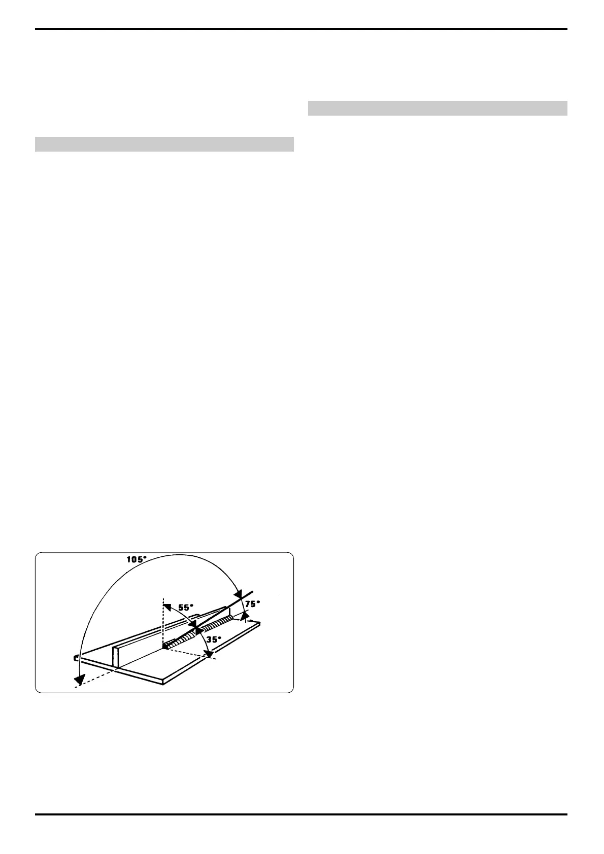
For the correct welding angle see figure.
5.2 WELDING ALUMINIUM
The welding machine must be prepared as for welding
mild steel with gas protection, but with the following diffe-
rences:
l 100% ARGON as the protection gas for welding.
l A wire having a composition suited to the base material
to be welded.
For welding ALLUMAN: 3÷5% silicon wire
l For welding ANTICORODAL: 3÷5% silicon wire
l For welding PERALUMAN: 5% magnesium wire
l For welding ERGAL: 5% magnesium wire
Use abrasive grinders and tool brushes specifically designed
for aluminium. Never use these tools on other materials.
REMEMBER that cleanliness equals quality.
The wire spools must be stored in plastic bags with a
dehumidifier.
See the figure for correct torch inclination.
5.3 WELDING STAINLESS STEEL
The welding machine must be prepared as for welding
mild steel with gas protection, but with the following diffe-
rences:
l Reel of stainless steel wire compatible with the compo-
sition of the material to be welded.
l Cylinder containing 98% ARGON + 2% 02 (recommen-
ded composition)
The recommended torch angle and welding direction are
shown in figure.
6 MAINTENANCE AND CHECKS
6.1 GENERAL NOTES
l Turn off the welding machine and unplug the power cord
from the socket before each checking and maintenance
operation.
l Moving parts can cause serious lesions
l Keep away from moving parts.
l INCANDESCENT SURFACES can cause serious burns.
l Let the unit cool before servicing.
l Periodically remove any dust or foreign matter that may
have deposited on the transformer or diodes; to do so, use
a jet of clean, dry air.
l When replacing the wire roller, make sure the groove is
aligned with the wire and corresponds to the diameter of
the wire used.
l Always keep the interior of the gas nozzle clean to avoid
metal bridges created by welding dross between the gas
nozzle and the contact tip. Make sure the outlet hole of the
contact tip has not expanded excessively; if so, replace.
l Strictly avoid striking the torch or allowing it to suffer vio-
lent impact.
6.2 REPAIRING THE WELDING MACHINE
Experience has shown that many accidents are caused by
repairs performed incorrectly. That is why it is just as
important to check a repaired welding machine carefully
and completely as it is for a new welding machine.
In addition, this protects the manufacturer from being held
liable for defects when the true fault lies elsewhere.
6.2.1 Instructions for performing repairs
l After rewinding the transformer or inductance, the wel-
ding machine must pass the applied voltage tests as indi-
cated in table 2 of paragraph 6.1.3 of the standard EN
60974.1 (CEI 26.13). Compliance must be verified as spe-
cified in 6.1.3.
l If no rewinding has been done, a welding machine that
has been cleaned and/or revised must pass an applied
voltage test with test voltage values equal to 50% of the
values given in table 2 of paragraph 6.1.3. Compliance
must be verified as specified in 6.1.3.
l After rewinding and/or replacing parts, the no-load vol-
tage must not exceed the values given in paragraph 10.1
of EN 60974.1.
l If the repairs have not been performed by the manufac-
turer, repaired welding machines in which some compo-
nents have been replaced or altered must be marked in
such a way that the person who performed the repairs is
clearly identifiable.
l After making repairs, take care to re-order the wiring so
that there is certain insulation between the primary side
and the secondary side of the machine. Prevent the wires
from coming into contact with moving parts or parts that
heat up during operation. Replace all clamps as on the ori-
ginal machine to prevent a connection from occurring
between the primary and secondary side if a conductor
accidentally breaks or disconnects.