3
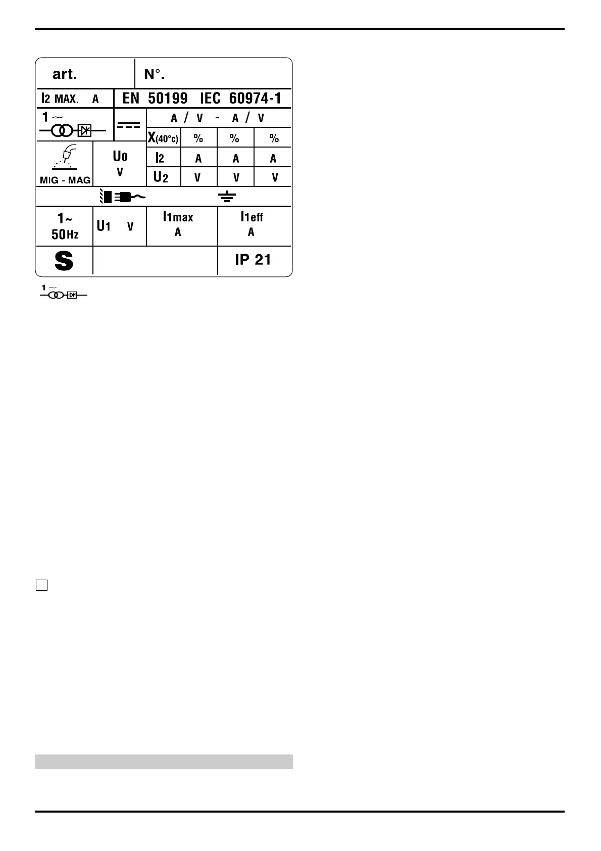
single-phase transformer-rectifier.
MIG/MAG. Suitable for continuous electrode welding.
I2 MAX Unconventional welding current.
The values represent the maximum levels
attainable in welding.
U0. Secondary open-circuit voltage.
X. Duty cycle percentage.
The duty cycle expresses the percentage
of 10 minutes during which the welding
machine may run at a certain current
without overheating.
I2. Welding current
U2. Secondary voltage with welding current
I2.
U1. Rated supply voltage
1~ 50Hz 50-Hz single-phase power supply.
I1 max. This is the maximum value of the rated
supply current.
I1 eff. This is the maximum value of the effective
input current, considering the duty cycle.
IP21 Protection rating for the housing.
Grade 1 as the second digit means that
this equipment is suitable for use out-
doors in the rain.
Suitable for use in high-risk environ-
ments.
NOTES:The welding machine has also been designed for use
in environments with a pollution rating of 3. (See IEC 664).
3.3 DESCRIPTION OF PROTECTION
This device is protected by a normally closed thermostat
on the power transformer.
When the thermostat is tripped the machine stops wel-
ding, while the motor-driven fan continues to run and the
yellow LED lights.
After it has been tripped, wait a few minutes to allow the
generator to cool down.
4 INSTALLATION
The machine must be installed by skilled personnel. All
S
connections must be made in compliance with current
regulations and in full respect of safety laws.
Make sure that the wire diameter corresponds to the one
indicated on the roller, and mount the wire reel. Make sure
that the welding wire passes through the groove in the
small roller 5.
Before connecting the power cable 29, make sure that the
power voltage corresponds to that of the welding machine,
then: a) for permanent connection to the power mains
without a plug, you must insert a main switch
having a suitable capacity in compliance with the
rated specifications.
b) for a plug-socket connection, use a plug having
a suitable capacity in compliance with the rated
specifications. In this case the plug must be used
to completely disconnect the machine from the
mains, after setting the switch 43 to “O” (off).
The yellow-green wire must be connected to the earth ter-
minal.
Connect the earth clamp 20 to the part to be welded.
The welding circuit must not be deliberately placed in
direct or indirect contact with the protection wire except in
the workpiece.
If the workpiece is deliberately grounded using the protec-
tion wire, the connection must be as direct as possible,
using a wire at least as large as the welding current return
wire, and connected to the workpiece at the same point as
the return wire, using the return wire clamp or a second
grounding clamp placed next to it.
All precautions must be taken to avoid stray welding cur-
rents.
Turn the machine on using the switch 43.
Remove the tapered gas tip by turning it clockwise.
Unscrew the contact tip.
Do not press the torch trigger until you have read the
instructions carefully.
It is important to make sure the machine is turned off whe-
never changing the wire reel and wire roller, to prevent the
wire feed motor from starting accidentally.
Press the torch trigger and release it only when the wel-
ding wire comes out.
Welding wire can cause puncture wounds.
Never aim the torch at parts of the body, other people or
metals when loading the welding wire.
Screw the contact tip back on, making sure that the hole
diameter corresponds to the wire used.
Slide the tapered gas welding tip on, always turning
clockwise.
4.1 CONNECTING THE GAS HOSE
l The gas cylinder must be equipped with a pressure
reducer and flow meter.
l If the cylinder is placed on the cylinder holder of the
machine, it must be held in place by the chain provided
and be of an appropriate size to avoid jeopardizing the
stability of the machine.
l Connect the gas hose leaving the back of the machine
to the pressure reducer only after the cylinder is in place.
l Open the gas cylinder and set the flow meter to approxi-
mately 8-10 lt./min.
CAUTION: Make sure the gas used is compatible with the
material to be welded.