EasyManua.ls Logo

Cebora TIG 2040 - User Manual

Cebora TIG 2040
76 pages
Go to English
Print Icon
To Next Page IconTo Next Page
Loading...
I -MANUALE DI ISTRUZIONI PER SALDATRICE AD ARCO pag. 2
GB -INSTRUCTION MANUAL FOR ARC WELDING MACHINE page 8
D -BEDIENUNGSANLEITUNG FÜR LICHTBOGENSCHWEISSMASCHINEN Seite 14
F -MANUEL D’INSTRUCTIONS POUR POSTES A SOUDER A L’ARC page 21
E -MANUAL DE INSTRUCCIONES PARA SOLDADORAS DE ARCO pag. 27
P -MANUAL DE INSTRUÇÕES PARA MÁQUINA DE SOLDAR A ARCO pag. 33
SF -KÄYTTÖOPAS KAARIHITSAUSLAITTEELLE sivu.39
DK -INSTRUKTIONSMANUAL FOR SVEJSEAPPARAT TIL BUESVEJSNING side.45
NL -GEBRUIKSAANWIJZING VOOR BOOGLASMACHINE pag.51
S -INSTRUKTIONSMANUAL FÖR BÅGSVETS sid.58
GR -ODHGOS CRHSEWS GIA SUSKEUHV TOXOEIDOUV" SUGKOVLLHSH" sel.64
Parti di ricambio e schema elettrico
Spare parts and electrical schematic
Ersatzteile und Schaltplan
Pièces détachées et schéma électrique
Partes de repuesto y esquema eléctrico
Partes sobressalentes e esquema eléctrico
Varaosat ja sähkökaavio
Reservedele og elskema
Reserveonderdelen en elektrisch schema
Reservdelar och elschema
Antallaktikav kai hlektrikov scediav-
gramma
Pagg. Seiten
sel.: 72-75
08/03/13
3.300.284/B
Question and Answer IconNeed help?

Do you have a question about the Cebora TIG 2040 and is the answer not in the manual?

Overview

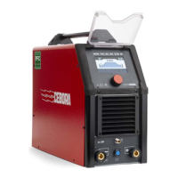
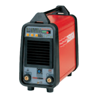
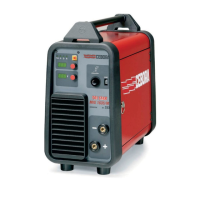
The Cebora Bi-Welder Tig 265 S is an arc welding machine designed for professional use in industrial environments. It operates as a constant direct current source, utilizing INVERTER technology. This machine is capable of welding with all types of coated electrodes (excluding cellulosic type) and supports TIG welding with both scratch start and high frequency. It is not intended for pipe defrosting.

Technical Specifications:

The machine complies with international standards IEC 60974-1, IEC 60974-3, IEC 60974-10 (CL. A), IEC 61000-3-12, and IEC 61000-3-11.

  • Power Supply: Single-phase, 50 or 60 Hz. The machine features an automatic supply voltage selector.
  • Rated Supply Voltage (U1): 1x230V-50/60Hz.
  • Maximum Absorbed Current (I1 max): This is the maximum value of the current absorbed.
  • Effective Absorbed Current (I1 eff): This is the maximum value of the actual current absorbed, considering the duty cycle.
  • Open-Circuit Voltage (U0): Secondary open-circuit voltage.
  • Welding Current (I2): Secondary voltage with current I2.
  • Duty Cycle (X): Percentage of 10 minutes during which the welding machine may run at a certain current without overheating.
  • Protection Rating (IP23S): The second digit '3' indicates that the equipment can be stored outdoors, but is not suitable for use in the rain unless protected.
  • Electromagnetic Compatibility: The machine is designed for environments with a pollution rating of 3 (IEC 60664). It complies with IEC 61000-3-11, provided that the maximum permissible system impedance Zmax at the interface point between the user's supply and the public system is less than or equal to 0.426. The installer or user is responsible for ensuring this connection requirement.

Function Description:

The front panel of the machine features several controls and indicators:

  • Procedure and Mode Selector Switch (A): A push-button to select the welding procedure (MMA or TIG) and mode. In TIG mode, two LEDs will always be lit: one indicating HF or striking start mode, and the other indicating continuous or pulse mode with 2- or 4-stage command.
    • MMA (B - LED): For Manual Metal Arc welding, suitable for all types of covered electrodes except cellulosic. Only knob O is enabled for current adjustment.
    • TIG without HF (C - LED): For TIG welding with arc started by touching the tungsten electrode to the workpiece.
    • TIG with HF (D - LED): For TIG welding with high-frequency pilot spark ignition.
    • Continuous 2-stage TIG (E - LED): Manual mode where current increases (slope up) when the torch trigger is pressed and decreases (slope down) when released. Compatible with pedal control (ART. 193).
    • Continuous 4-stage TIG (F - LED): Automatic mode where arc start and shut-off are controlled by pressing and releasing the torch trigger.
    • Continuous TIG with dual current level - 4 stages (G - LED): Automatic mode allowing two current levels to be set. The main current (X) and a second level (W) can be switched during welding by pressing and releasing the torch trigger.
    • Pulsed 2-stage TIG (H - LED): Manual pulsed TIG welding. The display P alternates between peak (main) current (X) and base current (W) for pulse frequencies up to 1.1Hz. Above 1.1Hz, it shows the mean of the two currents, and both X and W LEDs remain lit. Compatible with pedal control (ART. 193).
    • Pulsed 4-stage TIG (I - LED): Automatic pulsed TIG welding where arc start and shut-off are controlled by pressing and releasing the torch trigger.
    • Pulsed TIG with dual current level - 4 stages (L - LED): Automatic pulsed TIG welding with dual current levels, similar to mode G, but with pulsed current.
  • Knob (O): Adjusts the welding current. In combination with the R push-button, it can adjust:
    • Second level of current (W)
    • "Slope up" time (S)
    • "Slope down" time (U)
    • Pulse frequency (T)
    • Post gas time (V)
  • Display (P - 888): Shows welding current, settings selected with button R and adjusted with knob O, and block messages E1 and E2.
  • Selector (Q - MEM+/MEM-): Selects and saves programs. The machine can store nine welding programs (P01-P09) and a working program (PL).
  • Selector (R): When pressed, LEDs light up in succession, indicating parameters that can be adjusted with knob O.
    • Slope up (S - LED): Time for current to reach the set value from minimum (0-10 sec.).
    • Main welding current (X - LED): Indicates the main welding current.
    • Second level of welding or base current (W - LED): Always a percentage of the main current.
    • Pulse frequency (T - LED): (0.16-250 Hz). Peak and base times are equal.
    • Slope down (U - LED): Time for current to reach minimum and arc to shut off (0-10 sec.).
    • Post gas (V - LED): Time gas flows after welding ends (0-30 sec.).
  • 10-Pin Connector (Y): For connecting remote controls such as foot control (a), torch with start button (b), torch with potentiometer (c), or torch with up/down controls (d). The "ARC ON" function (clean contact 1A - 30V) is available between pins 3 and 6.
  • 1/4 Gas Fitting (Z): For connecting the TIG welding torch's gas hose.
  • Negative Output Terminal (AA):
  • Positive Output Terminal (AB):
  • Switch (AC): Turns the machine on and off.
  • Gas Intake Fitting (AD): For connecting the gas hose from the cylinder pressure regulator.

Usage Features:

  • Installation: Must be performed by skilled personnel according to current regulations and safety laws. Ensure correct supply voltage, adequate plug capacity, and proper earth connection.
  • MMA Welding: Connect the earth cable to the positive pole (+) and the electrode clamp to the negative pole (-), or vice versa depending on the electrode manufacturer's polarity requirements. Connect the earth clamp to the workpiece as close as possible to the weld area. Adjust current using knob O based on electrode diameter, welding position, and joint type.
  • TIG Welding: Connect the earth cable connector to the positive pole (+) and the clamp to the workpiece. Connect the TIG torch power connector to the negative pole (-). Connect the torch control connector to Y. Connect the torch gas hose to Z and the cylinder pressure regulator gas hose to AD.
  • Inert Gas Flow: Approximately 6 times the electrode diameter (in liters per minute). For gas-lens accessories, reduce to 3 times. Ceramic nozzle diameter should be 4 to 6 times the electrode diameter. ARGON is the most common gas, but ARGON-HYDROGEN (max 2% H2) for stainless steel or HELIUM/ARGON-HELIUM for copper can be used. For HELIUM gas, increase flow to 10 times the electrode diameter.
  • Memory Function: The machine can save up to nine welding programs (P01-P09) and a working program (PL). Programs can be selected and saved by pressing the Q button. A brief press selects, a press for more than 3 seconds saves.
  • Remote Controls: Various remote controls (foot control, UP/DOWN torches, potentiometers) can be connected to adjust welding current. Remote control settings are always active in the PL program but not in saved programs.

Maintenance Features:

  • General Maintenance: All maintenance must be performed by qualified personnel in compliance with IEC 60974-4.
  • Generator Maintenance: Before internal maintenance, ensure the AC switch is in "O" position and the power cord is disconnected. Periodically clean the interior of the machine from metal dust using compressed air.
  • Post-Repair Precautions: After repairs, ensure wiring is properly organized with secure insulation between primary and secondary circuits. Prevent wires from contacting moving or hot parts. Reassemble all clamps and screws with geared washers as per the original machine configuration.

Safety Precautions:

  • Arc Welding Hazards: Arc welding and cutting can be harmful. Users must be trained on associated risks.
  • Noise: The machine itself does not produce noise exceeding 80dB, but plasma cutting/welding may exceed this limit. Users must implement legal precautions.
  • Electromagnetic Fields (EMF): High currents create EMFs that can affect pacemakers. Individuals with pacemakers should consult a physician before welding. To minimize EMF exposure, route cables together, avoid coiling them around the body, and connect the earth cable close to the workpiece.
  • Explosions: Do not weld near pressure vessels or explosive dust/gases. Handle gas cylinders and regulators with care.
  • Electric Shock: Wear dry insulating gloves. Do not touch the electrode with bare hands or wet/damaged gloves. Ensure insulation from the workpiece and ground. Disconnect the input plug before working on the machine.
  • Fumes: Welding fumes are hazardous. Keep your head out of fumes and use forced ventilation or local exhaust to remove them.
  • Sparks and Fire: Welding sparks can cause explosions or fires. Keep flammable materials away, have a fire extinguisher nearby, and do not weld on closed containers.
  • Arc Rays: Arc rays can burn eyes and injure skin. Wear a welding helmet with the correct shade filter, safety glasses, ear protection, and complete body protection.
  • Labels: Do not remove or paint over warning labels.
  • Malfunctions: In case of malfunctions, request assistance from qualified personnel.

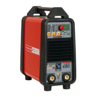
The Cebora Bi-Welder Tig 265 S is a robust and versatile welding machine, offering advanced features for professional TIG and MMA welding applications, with a strong emphasis on safety and user-friendly controls.

Cebora TIG 2040 Specifications

General IconGeneral
BrandCebora
ModelTIG 2040
CategoryWelding System
LanguageEnglish

Related product manuals