(180). Use a hydraulic press to press the bearing
cartridge (180) from the bearing housing (26).
2) RA3146 procedure:
The bearing cartridge (180) has two
3
/8"-16 UNC tapped
holes that are accessible from the impeller end of the bear-
ing housing. Securely bolt a
1
/2" Class 300 flange to the
cartridge, using washers on the bolts. Use a 14” long
piece of 1” pipe (1
5
/16" outside diameter), cut square on
the ends, to reach down through the bearing housing (26)
to press the bearing cartridge out.
3) RA3186 procedure:
The bearing cartridge (180) has two
1
/2"-13 UNC tapped
holes that are accessible from the impeller end of the bear-
ing housing. Securely bolt a 1” Class 300 flange to the
cartridge, using washers on the bolts. Use a 22” long
piece of 1
1
/4" pipe (1
5
/8"outside diameter), cut square on
the ends, to reach down through the bearing housing (26)
to press the bearing cartridge out.
l) Remove the seal vent plug from the top of the bearing housing
(26) and discard it. The RA2096 and RA3146 pumps have a
3
/8" plug and the RA3186 pumps have a
1
/2" plug. Refer to
the drawings on page 6.
m) If there is any reason to remove the bearing housing foot (9),
it is secured by two bolts and located by a dowel pin.
REASSEMBLY PROCEDURE
WARNING:
Use only high quality tools.
Wear protective equipment as advised at the beginning of this
section.
Use mechanical lifting equipment to lift assemblies and
components.
Do not hammer on any parts. Personal injury and/or damage to
equipment may occur.
Do not attempt to manufacture parts or modify Dean Pump parts in
any manner. Death, personal injury, and/or damage to
equipment may occur.
Replace all gaskets, seals, bearings, and lubricants. Replace all
parts that have worn, corroded, eroded, or otherwise deteriorated.
Use only Dean Pump Division of Met-Pro Corporation parts.
To reassemble the pump, perform the following steps:
a) Clean all parts, thoroughly inspect them, and replace where
necessary. If the pump shaft (29) has two lip contact wear pat-
terns (lip seal contact area) under the lip seal (76), replace the
shaft. If the shaft is scored under the bearing (180), replace the
shaft.
b) Install a new seal vent plug into the top of the bearing housing
(26), but do not apply any pipe sealant, and do not tighten the
plug. The plug will need to be removed again later, for vent-
ing, when the pump is installed into the system. Refer to the
drawings on page 6.
c) Press a new bearing cartridge (180) into the bearing housing
(26) until it seats firmly against the shoulder in the bearing
housing. On the RA2096, install with the exposed carbon
bearing face facing outward (see sectional assembly draw-
ing). On the RA3146 and RA3186, install with the two tapped
holes facing outward and the
1
/8" diameter “through hole”
positioned at the top of the bearing housing (see sectional
assembly drawing). Use a press and a pad over the end of the
bearing cartridge (180). Do not hammer on the bearing
cartridge; the bearing could be broken. If a press is not avail-
able, the bearing cartridge could be pulled into the bearing
housing by using a piece of threaded rod through the bearing
housing with a large washer and a nut on each end.
d) If the pump is a RA3146, install the snap ring (75) onto
the pump shaft (29) insuring that it is securely into the snap
ring groove.
e) If you are reinstalling a previously used pump shaft (29),
inspect the shaft for wear under the grease seal(s) as directed
in paragraphs h) and r) below. Press the thrust bearing(s) (25A)
onto the pump shaft (29).
1) RA2096 procedure:
Press the thrust bearing (25A) onto the pump shaft
(29) and firmly against the shaft shoulder. Do not hammer
on the bearing or shaft in any manner as this will
cause damage.
2) RA3146 procedure:
Press the thrust bearings (25A) onto the pump shaft (29)
and firmly against the snap ring (75). The thrust bearings
are angular-contact type, ground specifically for duplex
mounting and must be assembled back-to-back (see the
illustration below). Note the direction that the races of the
bearing are mounted. Do not hammer on the bearings or
shaft in any manner as this will cause damage.
3) RA3186 procedure:
Press the thrust bearings (25A) onto the pump shaft (29)
and firmly against the shaft shoulder. The thrust bearings
are angular-contact type, ground specifically for duplex
mounting and must be assembled back-to-back (see the
illustration below). Note the direction that the races of the
bearing are mounted. Do not hammer on the bearings or
shaft in any manner as this will cause damage.
f) Secure the thrust bearing(s) (25A) to the pump shaft (29).
1) RA2096 procedure:
Install the bearing retaining snap ring (75A) with tapered
side away from the bearing (see illustration on page 16).
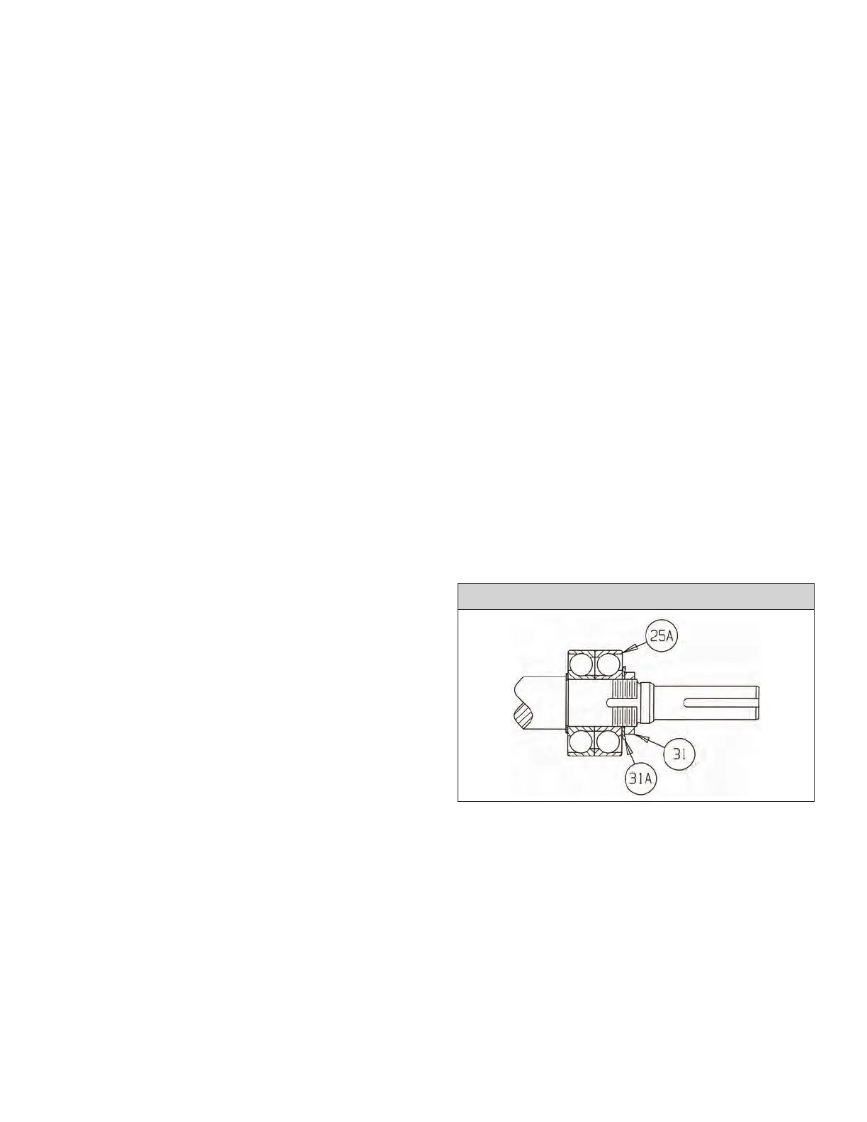
2) RA3146 and RA3186 procedure:
Install a new bearing lock nut washer (31A). Install the
bearing lock nut (31). Bend a tab of the bearing lock nut
washer (31A) into an aligned slot of the bearing lock
nut (31).
15
THRUST BEARING POSITION - RA3146 AND RA3186
 Loading...