16
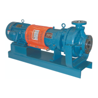
SNAP RING ORIENTATION - RA2096
g) Thrust bearing lubrication.
1) RA2096 procedure:
The thrust bearing(25A) of the RA2096 is already packed
with grease and is sealed for life.
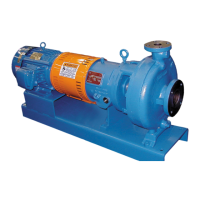
2) RA3146 and RA3186 procedure:
Pack the thrust bearings (25A) with grease.
The RA3146 requires 2.9 cubic inches of grease.
The RA3186 requires 6.8 cubic inches of grease.
Attempt to force all of the grease into the bearings. The
grease must be a lithium 12-hydroxystearate soap thick-
ened grease that has rust inhibitors and extreme pressure
additives and must be a NLG1, Grade 2, similar to
Shell Oil Company’s “Alvania” Grease #EP2 or
Union Oil of California’s “UNOBA #EP” Grease
Grade 2
Grease is also available from Dean Pump in individual
containers, Order RA3000 Grease #2 for bearing
lubrication. One container is required for each
RA3146 pump. Two containers are required for each
RA3186 pump.
h) Press a new grease seal (76) into the mechanical seal gland
(13). Remove and discard the garder spring from a new
grease seal (76). Install with the lip pointing towards the
impeller end of the pump as shown in the pump sectional
assembly drawing.
Inspect the shaft (29) when installing a used shaft (if the shaft
has been used before): determine if there is one or two grease
seal lip contact wear patterns (grease seal lip contact area). If
two contact areas are present, the pump shaft needs replacing.
If one contact area is present, stop pressing on the seal when
the outside face of the seal is
1
/16" above the face of the
mechanical seal gland (13). If the pump shaft (29) is new,
press the seal into the mechanical seal gland (13) until it is
flush with the face of the mechanical seal gland.
i) Install new seal gland gaskets (325) into the mechanical seal
gland (13). Lubricate the gaskets before installing, with an oil
that is compatible with the liquid to be pumped, or with the
pumped liquid itself.
j) Install a new mechanical seal stationary seat (95A) into the
mechanical seal gland (13). If the pump is a RA2096 or a
RA3146, be sure that there is an “O” ring installed in the
groove in the outside diameter of the mechanical seal station-
ary seat (95A). If the pump is a RA3186, install the stationary
seat “O” ring (the “O” ring is furnished with the mechanical
seal stationary seat) into the groove in the bore of the mechan-
ical seal gland (13). Install the mechanical seal stationary seat
(95A) with the polished face away from the lip seal (76).
Lubricate the “O” ring before installing the mechanical seal sta-
tionary seat (95A) into the seal gland (13). An oil compatible
with the liquid to be pumped, or the pumped liquid itself,
should be used as a lubricant for the “O” ring.
k) Lubricate the area of the shaft over which the lip seal will slide,
then carefully slide the mechanical seal gland (13) assembly
over the shaft, so as not to damage the lip seal (76) nor the
mechanical seal stationary seat (95A). Push the mechanical
seal gland snugly against the thrust bearing (25A).
l) Lubricate the area of the shaft over which the mechanical seal
rotary (95B) will slide. Carefully slide the mechanical seal
rotary (95B) over the shaft (29) until it contacts the mechanical
seal stationary (95A). Do not damage the seal on any of the
shaft shoulders.
m) Slide the mechanical seal collar (365) carefully over the shaft
(29) until it is firmly against the shaft shoulder and compressing
the spring of the mechanical seal rotary (95B). Tighten the set
screws while holding the seal collar (365) firmly against the
shaft shoulder.
n) Lubricate the bore in the back of the bearing housing (26) so
that the seal gland gaskets (325) will slide in without damage.
Carefully slide the shaft assembly (29) into the bearing housing
(26) from the bearing end cover end. Do not strike the carbon
bearing (180) with the end of the pump shaft (29). Guide the
mechanical seal gland (13) and the thrust bearings (25A) into
the bearing housing (26) as the shaft assembly (29) is installed.
p) If the pump is a RA2096 go to step w.
q) Install a new end cover gasket (77B) over the thrust bearing
(25A) and against the bearing housing (26).
r) Remove the garter spring from a new lip seal (76A) and dis-
card it. Press the lip seal into the bearing end cover (28), from
the bearing side, and up against the shoulder at the opposite
side, when a new shaft is being used. If the pump shaft is not
new, stop pressing on the lip seal
1
/16" before it reaches the
shoulder of the end cover, placing the sealing lip at a new loca-
tion on the pump shaft (29).
s) Lubricate the pump shaft (29) at the diameter where the lip seal
(76A) contacts. Apply any remaining grease from packing the
thrust bearings (25A) around the exposed face of the bearings
(25A). Place the end cover (28) carefully over the pump shaft
(29) and the thrust bearing (25A), with the plugged hole
towards the baseplate. Bolt the end cover (28) securely to the
bearing housing (26). Torque the end cover bolts to 20 lb.ft. on
the RA3146 and to 35 lb. ft. on the RA3186.
RA3146 AND RA3186 FAN LOCATIONS
 Loading...