t) Mark (pencil or light scribe) a line on the pump shaft (29),
3
1
/4" for the RA3146 and 5
1
/16" for the RA3186, from the
coupling end. Place the fan collar (121), grooved face first,
onto the pump shaft and up to the “mark”. Refer to the
drawing on bottom of page 16. Tighten the fan collar locking
screw tightly.
Place the fan (120), with the concave side of the blades
towards the pump, over the end of the pump shaft (29) and up
against the fan collar (121). The concave side of the fan blade
was indicated with a label “PUMP SIDE” at the time it was
shipped from the factory. Rotate the fan until the holes in the
fan align with the tapped holes in the fan collar.
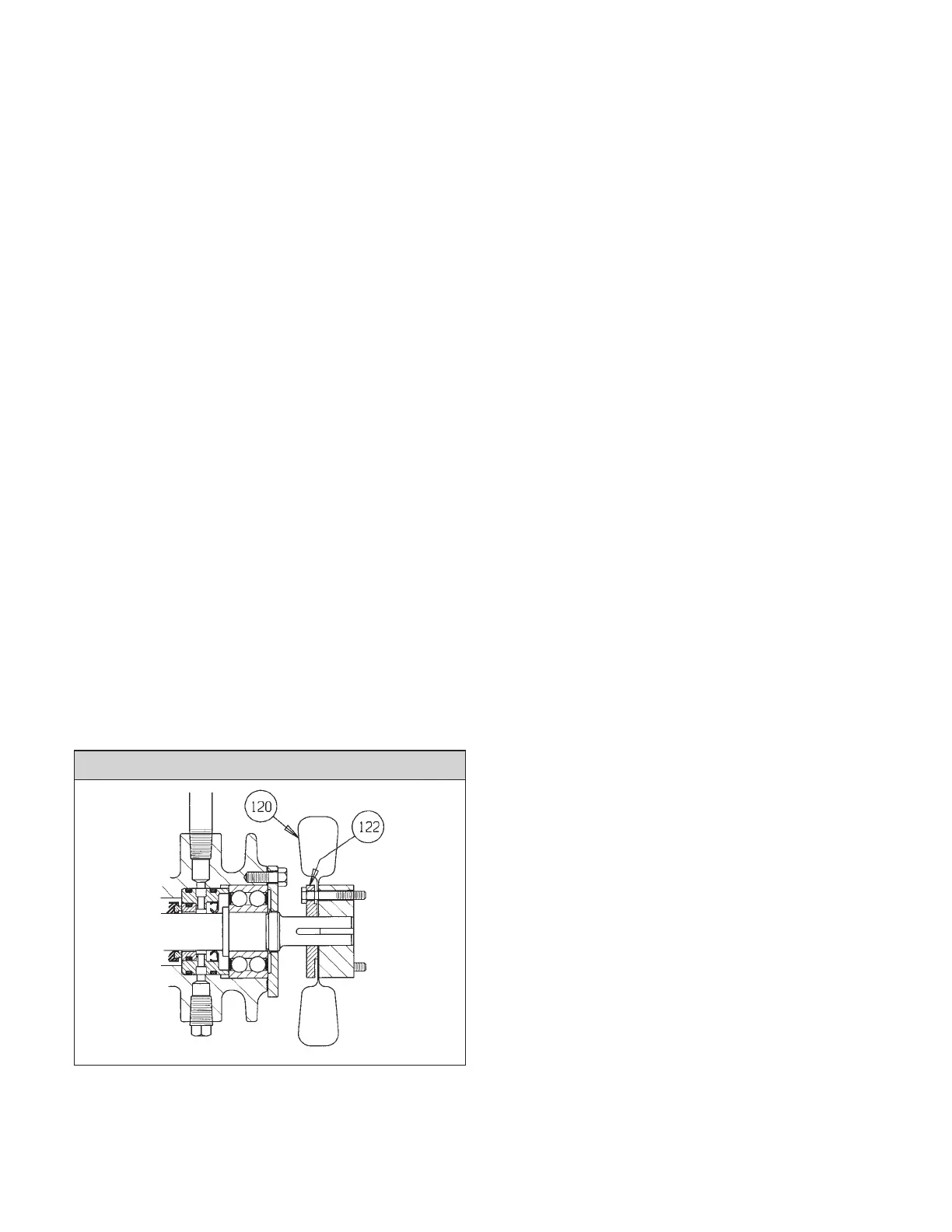
Place the fan clamp ring (122) over the end of the pump shaft
(29) and up against the fan (120). Align the holes in the fan
clamp ring with the holes in the fan and the holes in the fan
collar (121).
Insert the two socket head bolts, with lock washers, through the
fan clamp ring (122) and the fan (120), into the tapped holes
of the fan collar (121) and tighten them securely.
u) Insert the coupling bolts through the lockwashers and the pump
coupling hub. Place the hub onto the pump shaft (29), posi-
tioning the outer face of the hub flush with the end of the pump
shaft. Install the coupling key and tighten the hub set screw(s).
v) Go to step z).
w) Place the end cover (28) carefully over the pump shaft (29)
and bolt it securely into position against the bearing housing
(26). Torque the end cover bolts to 11 lb.ft.
x) Insert the four coupling bolts through the lockwashers and the
fan clamp ring (122) from the side opposite of the raised face.
The clamp ring is made to fit three different sizes of couplings,
so you must insert the bolts into the holes that match the cou-
pling hub that you are using. Slide the clamp ring onto the
pump shaft (29) with the raised face facing the motor.
Place the fan (120), with the concave side of the blades towards
the pump, over the end of the pump shaft, onto the coupling bolts
and up against the clamp ring. Refer to the drawing below. The
concave side of the fan blade was indicated with a label “PUMP
SIDE” at the time it was shipped from the factory.
y) Place the coupling hub over the end of the pump shaft (29) and
onto the coupling bolts, until the face of the hub is flush with the
end of the pump shaft. Install the coupling key, with the end of
the key flush with the end of the pump shaft and the face of the
hub. Tighten the hub set screw(s).
z) Place the impeller key (4) into the keyway of the pump shaft (29).
Carefully slide the impeller (3) onto the pump shaft (29).
1) If the pump is a RA2096,
slide the impeller washer (12A) over the pump shaft (29)
and against the impeller (3). Thread one of the impeller nuts
(12) onto the pump shaft (29) and tighten it to a torque of
40 Lb.Ft. Thread the second impeller nut (12) onto the end
of the pump shaft (29) and tighten it to a torque of 40 Lb.Ft.
Hold the pump shaft (29), against the tightening torque, by
placing a wrench on the flats of the coupling hub. Be care-
ful to not bend the blades of the fan (120).
2) If the pump is a RA3146 or a RA3186,
Place the impeller washer (12A) on to the impeller bolt (12)
and thread the impeller bolt (12) into the end of the pump
shaft (29). Tighten the impeller bolt to a torque of 60 lb. ft.
for the RA3146 and 100 lb. ft. for the RA3186. Hold the
pump shaft, against the tightening torque, by placing a
wrench on the flats of the coupling hub. Be careful to not
bend the blades of the fan (120).
aa) If the pump has a casing ring (6A), press it into the casing (5).
ab) Carefully insert the bearing housing (26) assembly into the
casing with a new casing gasket (77). Assure that the bearing
housing (26) assembly is fully into the casing (5) and that the
bearing housing foot (9) is in full contact with the baseplate.
Tighten the casing capscrews (5D) or the casing stud nuts (5C)
slowly and evenly so that the casing gasket will compress even-
ly. Torque the casing capscrews (5D) of the RA2096 pumps to
50 lb. ft. Torque the casing stud nuts (5C) of the RA3146 and
RA3186 pumps to 105 lb. ft. if the studs are
3
/4” and to 165 lb.
ft. if the studs are
7
/8”.
ac) Rotate the pump shaft (29) by hand to check for interference.
Wear heavy gloves when rotating the shaft, to protect your
hands. Correct if any rubbing is detected.
ad) If the casing (5) was removed from the baseplate, reattach it with
bolts through the casing feet to the baseplate. Reattach the suc-
tion and discharge flanges, installing new gaskets.
ae) Bolt the bearing housing foot to the baseplate. Rotate the pump
shaft (29) again by hand to check for rubbing. Wear heavy
gloves when rotating the shaft, to protect your hands. Correct if
any rubbing is detected.
af) Realign the pump and driver per instructions under “PUMP AND
DRIVER ALIGNMENT”.
ag) Follow the instructions under “PUMP LUBRICATION”, “START-
ING THE PUMP”, and “PUMP START UP CHECKLIST”.
RA2096
17
 Loading...