5
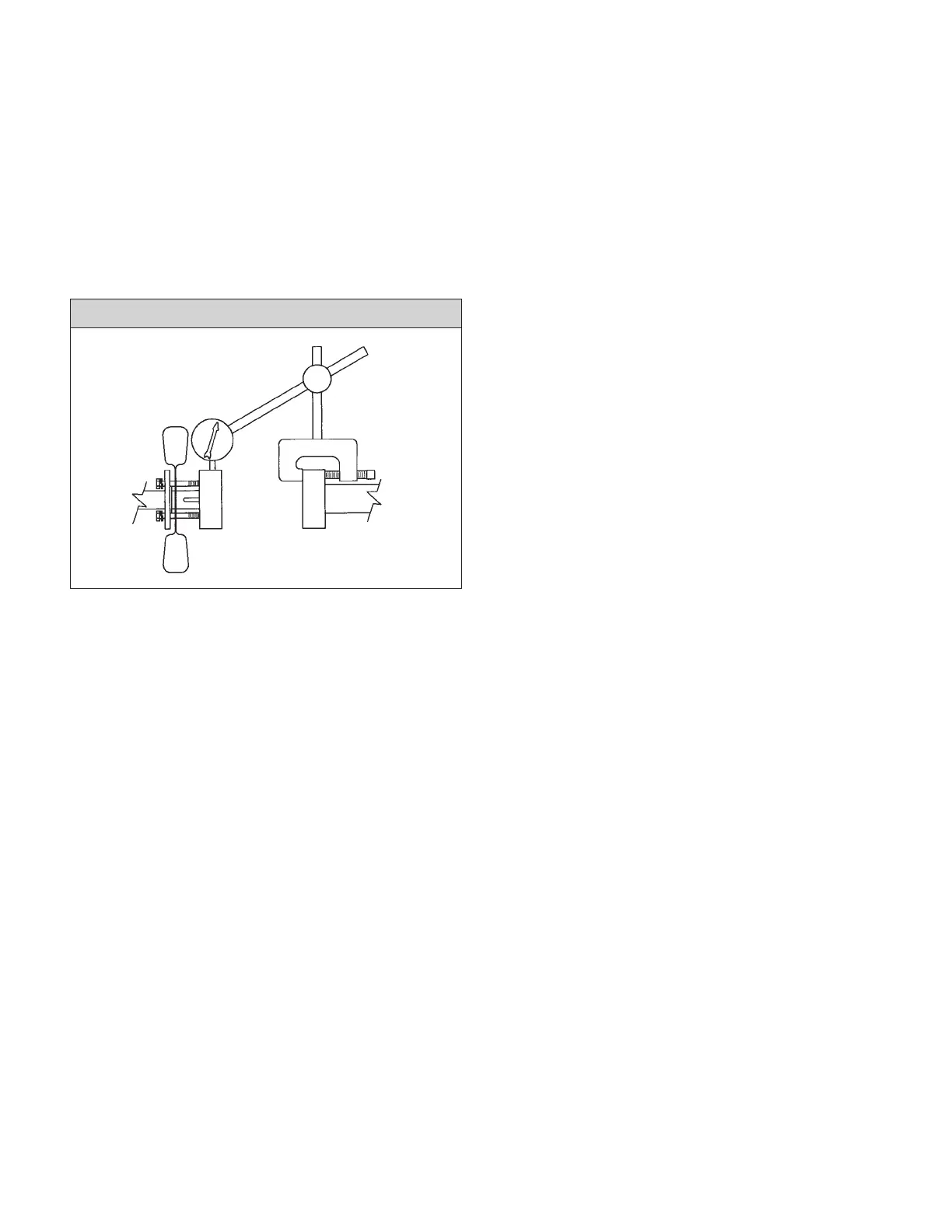
To check the offset alignment, mount the dial indicator as shown in
the illustration “INDICATOR SETUP TO READ OFFSET MISALIGN-
MENT” below, with the indicator button on the outside diameter of
the stationary hub, near the face of the hub closest to the end of the
shaft. It may be necessary, on the RA2096 pumps, to slide the cool-
ing fan (120) closer to the pump, to obtain enough clearance for
the dial indicator, dependent of course upon the type of indicator
used. If necessary, the fan could be removed, and replaced after
the motor alignment is completed. Rotate the shaft, to which the dial
indicator is clamped, allowing the indicator button to ride on the
outside diameter of the stationary coupling hub. The indicator dial
move ment will show the difference in the center locations of the two
shafts. Good practice suggest alignment to within 0.002" T.I.R.
Angular and offset alignment is adjusted by moving the motor side-
ways and up and down to bring the motor into exact alignment
with the bolted down pump. The motor is moved up and down by
adding and removing thin metal shims between the motor feet and
the baseplate. If misalignment is of major proportions, the base-
plate has been improperly installed on the foundation and must be
releveled before proceeding with alignment.
After each change, it is necessary to recheck both angular and off-
set alignment of the coupling. After the pump and driver are
aligned, tighten all hold-down bolts and then recheck alignment.
The closer the running alignment, the longer the running life will be.
INDICATOR SETUP TO READ OFFSET MISALIGNMENT