Safe2+ / Safe4 Operation Manual
10 www.cedes.com © CEDES Safety & Automation AG / June 2008
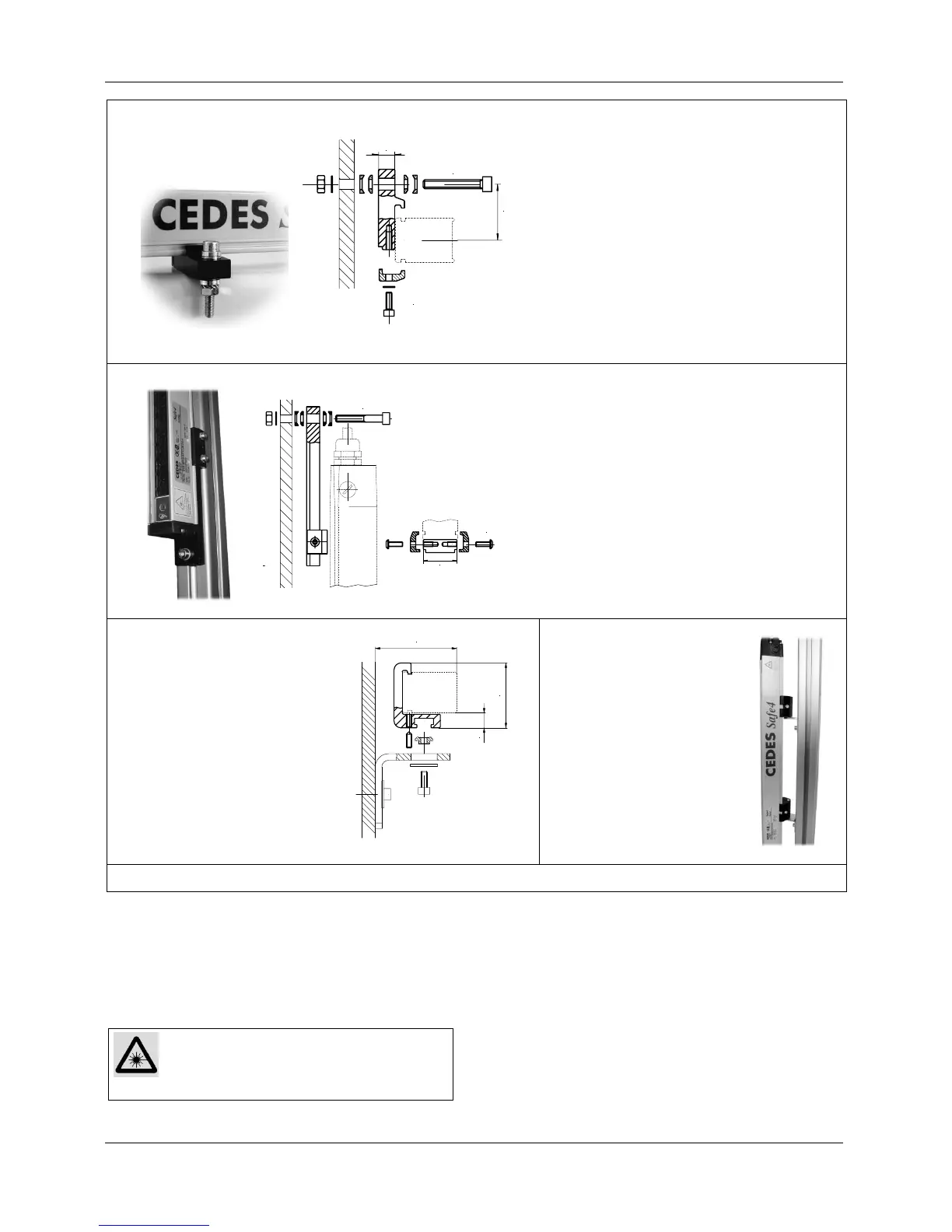
The mounting brackets contain all necessary mount-
ing parts and an separate instruction sheet to en-
sure that the parts are assembled properly.
5.2.2. Intelligent Laser Alignment System
ILAS (Optional with Safe2+)
WARNING: Class 2 Laser
Do not expose your eyes to the laser to
prevent exposition to dangerous laser ra-
diation! Turn ILAS off if not used!
To switch on ILAS: Touch the hand symbol $
Operation: Laser beam is blinking
To switch off ILAS:
• Touch the hand symbol $ again
• Automatically after 5 minutes
5.2.3. Adjustment Procedure without ILAS
1. Mount the emitter and the receiver with the ad-
justable mounting brackets. Make sure that the
longitudinal axis of both are oriented parallel. A
spirit level might help to find the correct posi-
tion.
11
29.5
M6 x 40
M4 x 16
Mounting kit 30mm (2 brackets)
Part No. 106 500
• For side mounting
• Adjustable by ± 4°
29
M4 x 12
M6 x 40
Mounting kit vertical 30mm (2 brackets)
Part No. 106 502
• For mounting in the vertical axis of the
light curtain
• Adjustable by ± 4°
FGS mounting profile
Part No. 106 503
• A special profile which is
compatible with existing
FGS-mountings.
• Adjustments has to be
made with the FGS-
mountings, if available.
47.5
60
11
Mounting kit 180° adj.
30mm (2 brackets)
Part No. 106 497
180° Mounting, rotation ±
90°, for applications where
the mounting angle is not set
using the mounting frame.
Figure 12: Different mounting brackets for a Safe2+ / Safe4