Safe2+ / Safe4 Operation Manual
12 www.cedes.com © CEDES Safety & Automation AG / June 2008
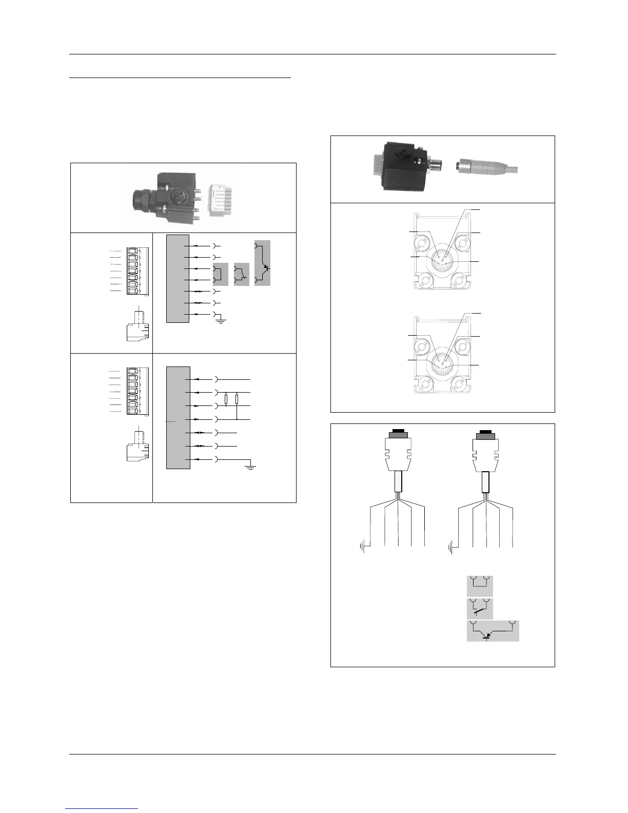
5.3. Electrical Installation
The emitter and receiver are connected to the ma-
chine control using a 5-wire cable.
5.3.1. A connector cap
For the emitter and the receiver two M12 (for cable -
Ø 3 ... 6.5 mm) an two M16 cable glands (for cable -
Ø 3.5 ... 10 mm) are supplied.
Emitter Tx
1
2
3
4
5
6
7
1)
3)
2)
Reveiver Rx
1
2
3
5
4
6
7
Figure 16: Terminal block connection
(see also Figure 22)
5.3.2. B connector cap
The B connector cap M12/5-pole plug connector
provides easy connection of a cable assembly. The
plug pin assignment is shown in Diagram 18.
Figure 17: M12/5 Pin connector
+24 VDC
0 V
OSSD 1
OSSD 2
+24 VDC
0 V
1) Operation with internal test
2) Test using a relay contact
3) Test using PNP output
Emitter
3)
2)
PE
Lumberg 1 (brown)
Lumberg 3 (blue)
Lumberg 4 (black)
Lumberg 2 (white)
Lumberg 5 (grey)
Receiver
PE
Lumberg 1 (brown)
Lumberg 3 (blue)
Lumberg 4 (black)
Lumberg 2 (white)
Lumberg 5 (grey)
1)
Test 1
Test 2
Figure 18: Wiring of the connecting cables of the M12/5 Pin
Lumberg connector (Part no. cable: 301 347)
The wiring of such connecting plugs is given in fig-
ure 17 and figure 18.
24 VDC
0 VDC
Test 1
Test 2
Not connected
Not connected
GND
24 VDC
0 VDC
Not connected
Not connected
GND
1. Operation with internal test
2. Test using a relay contact
3. Test using a PNP output
24 VDC
0 VDC
Not connected
Not connected
GND
OSSD 1
OSSD 2
24 VDC
0 VDC
OSSD 1
OSSD 2
Not connected
Not connected
GND
GND
0V
Test 2
Test 1
+ 24 VDC
Emitter Tx
Reveiver Rx
OSSD1
+ 24 VDC
OSSD2
0V
GND