Safe2+ / Safe4 Operation Manual
6 www.cedes.com © CEDES Safety & Automation AG / June 2008
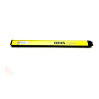
4.4. Cascading
Safe2+ or Safe4 allows one or several extension
modules to be connected by daisy-chaining to a
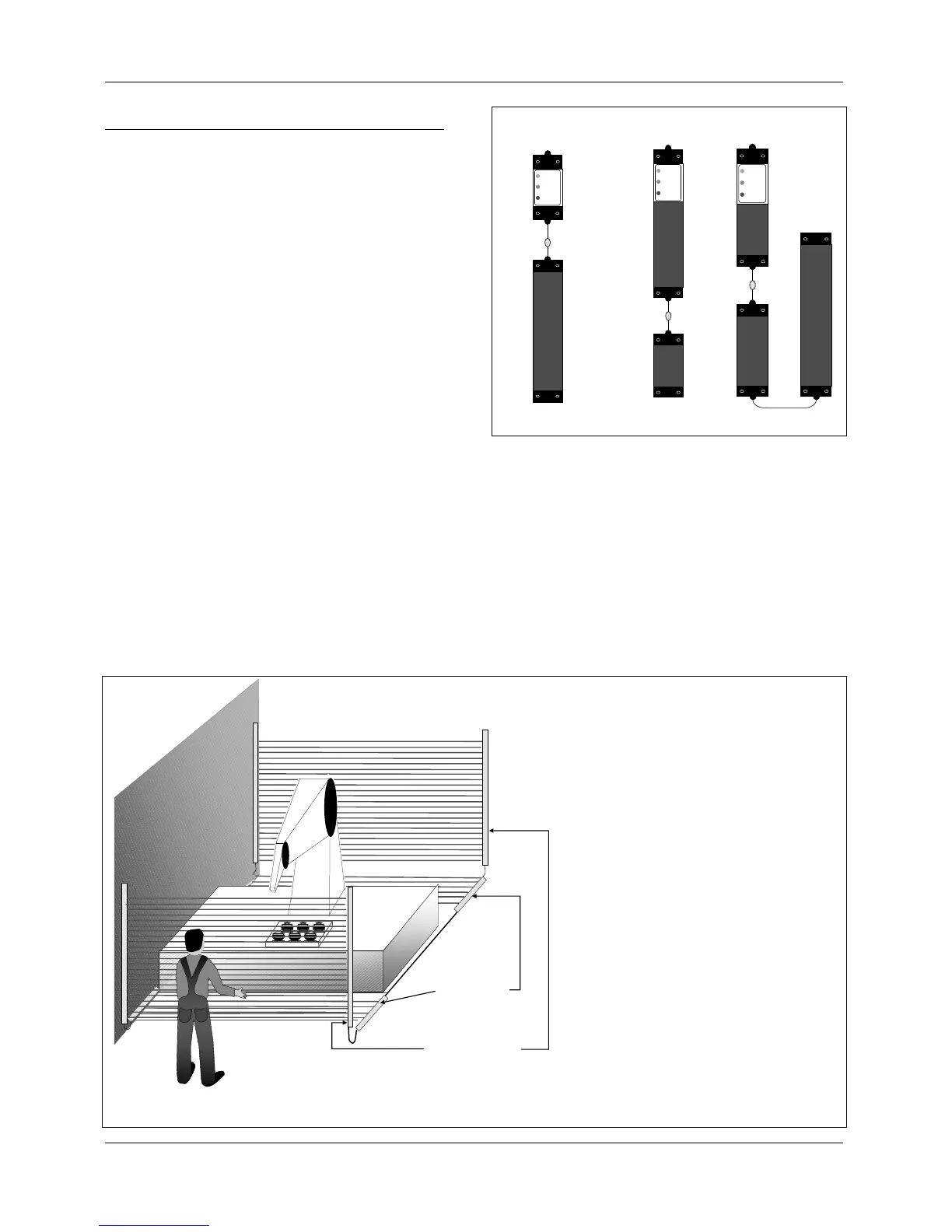
complete system (Figure 7). This can be used to
prevent someone from standing between the safety
device and the danger point (Figure 4). Any combi-
nations are possible, even mixed resolutions 14 / 30
mm. In every extension module an ILAS is integrated
for the simple and comfortable alignment depending
on the type (Safe2+ or Safe4) .
Following limitations shall be taken into considera-
tion:
• Maximum 256 light beams per controller
• The protective zone is made of units with
120 mm length
• 8 beams are used per unit with 30 mm resolution
• 16 beams are used per unit with 14 mm resolution
• 10 m maximum total length for light curtains, ex-
tension modules and connection cables combined
(Figure 8)
• Max. three ILAS may be operated simultaneously
• Only a CEDES prefabricated cable may be used
between the light curtains.
The extension modules are connected to the main
system via connection cables.
The customers defines:
• Main system (protective height, resolution, operat-
ing range)
• Length of connection cables
• Extension modules (protective height, resolution,
operating range)
• Accessories (mounting kit, electrical ports)
Due to safety reasons combined light curtain as de-
scribed above have to be configured and tested as
complete configuration by the manufacturer.
2 x entry safeguarding
2 x hazardous zone
safeguarding
System length:
2 x length of hazardous zone safeguarding
+ 2 x length of entry safeguarding
+ 1 x length of connection cable
-----------------------------------------------
Total length (max. 10 m)
Figure 8: Connection of the back and the front side of a machine with only one Safe2+ / Safe4 cascading system. The total length of the
system is equal to the individual protective field lengths, plus connection cables added together.
Separated
Controller
2 protective
fields
3protective
fields
Figure 7: Possible configurations