8
Attach the mounting brackets
each with the enclosed 4 screws
(5x40 mm) and 4 dowels to your
solid concrete or solid brick wall.
(Fig. 1) For other load-bearing
structures use suitable moun-
ting accessories! If you are unsure
about the correct and safe attach-
ment to your supporting structure
(e.g. wood, plasterboard, hollow
brick wall etc.) have the installation
work carried out by a specialised
installer!
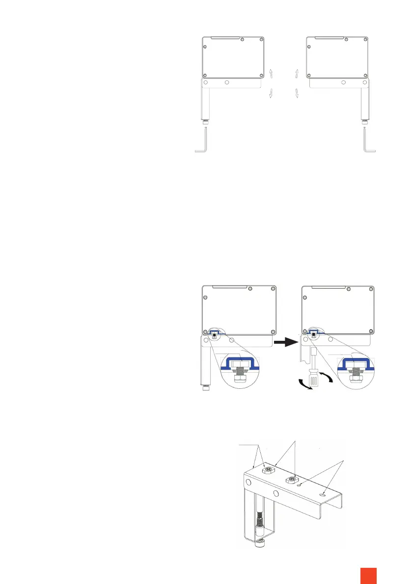
INSTALLATION OF THE SCREEN
Now use 2 people to carefully place
the screen carefully onto the support
surfaces of the mounting brackets,
so that the power supply points to
the right-hand side. Slowly lower the
screen and check the stability of
the mounting brackets on your wall.
Align the locking screws parallel to
the wall/furniture beforehand so
that they t into the grooves in the
screen base. Tighten the nylon nuts
on the thread of the locking screws
underneath the mounting brackets
hand-tight. In doing so the locking
screw is rotated by approx. 90 de-
grees and xed in the screen housing
to prevent the screen from falling
down. (Fig. 4)
Adjustable +-1.5°
Fig. 3
Locking
screw
Locking
screw
Insert into
the groove
Turn to x
Fig. 4
Locking screw
Inverted mounting
holes
Level
Fig. 5
Installation
on wall
Installation on
furniture back
panel