REV. 01
13 / 28
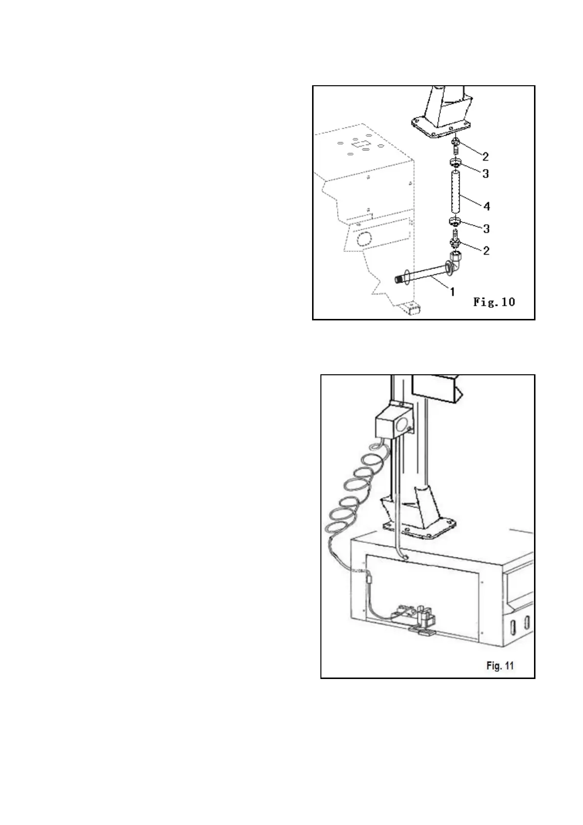
4.2.2 Mounting and connecting the GT
• Route the tube (1), situated inside the
machine body, though the hole on the back
side of the body.
• Connect the hose (4) to the connectors (2)
using the bands (3).
4.2.3 Mounting and connecting the manometer
• Fix the manometer to the vertical arm
through the proper screw. Fig. 11.
• Route the connecting spiral hose through the
small hole on the back side of the machine
body.
• Connect the rilsan hose to the union of the
pressure limiting device, situated on the
inflating pedal.
 Loading...