Page 10 For technical questions, please call 1-888-866-5797. Item 64981
Taking a Reading
Note: Do not replace a part based solely on the DTC definition� Each DTC has a set of
test procedures, instructions, and flow charts that must be followed to confirm the cause
of the problem� Refer to the vehicle’s service manual for detailed testing instructions�
Notice: Observe all safety precautions
before working on a vehicle.
1� Turn off the vehicle’s ignition
and connect the Code Reader’s
16-pin OBD II Cable to the
vehicle’s DLC connector�
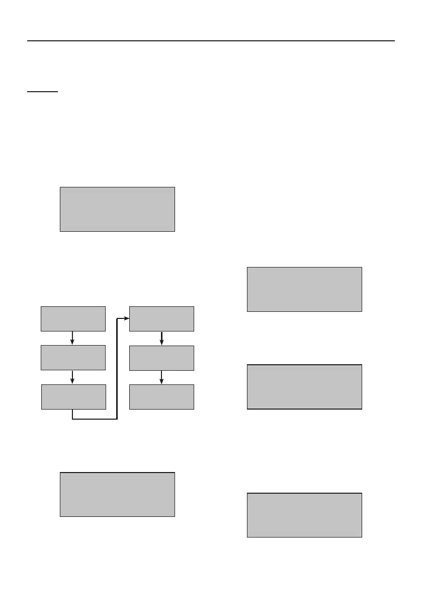
2� The display will indicate when
the Code Reader is ready:
CAN OBDII
KC20
Figure D: Ready Screen
3� Press ENTER/Exit and a sequence
of messages showing the OBD II
protocols will step through until the
vehicle’s protocol is detected:
SCAN
CAN STD
SCAN
CAN EXD
SCAN
PWM
SCAN
VPW
SCAN
KWP2000
SCAN
ISO9141
Figure E: : Protocol Detection Sequence
4� The messages will end at the
vehicle’s detected protocol:
SCAN
ISO9141
Figure F: Example of Vehicle’s
Detected Protocol
5� If the Link Error! message displays:
a� Turn off the ignition for 10 seconds
and check that the Code Reader’s
ODB II Cable is well seated into
the vehicle’s DLC connector�
b� Turn ignition to ACC and
repeat protocol detection�
c� If the error does not clear then there
is a communication problem between
the Code Reader and vehicle�
6� After the detected protocol is displayed,
the scanning results will appear� The
total number of DTCs and overall
I/M Monitor Status will be shown:
DTC: 10
IM: YES
Figure G: Example of Scan Results
7� Next, the screen will display the
Main Menu’s first selection:
MENU:
1. DTC
Figure H: DTC Screen
8� Press ENTER/Exit to select “DTC�”
9� If no Diagnostic Trouble Codes were
detected the green light will illuminate
and the display will indicate:
NO
CODES
Figure I: No DTCs detected