9
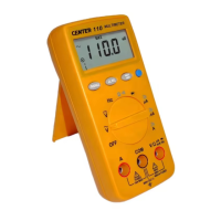
⊂ Connect the red test lead to the anode
side and black test lead to the cathode
side of the diode being tested.
⊆ Read forward Voltage( V
f
) value on
LCD.
∈ If the polarity of test leads are reversed
with diode polarity ⊂, the digital reading
show “ OL ”.This can be used for
distinguishing anode and cathode
terminal of a diode.
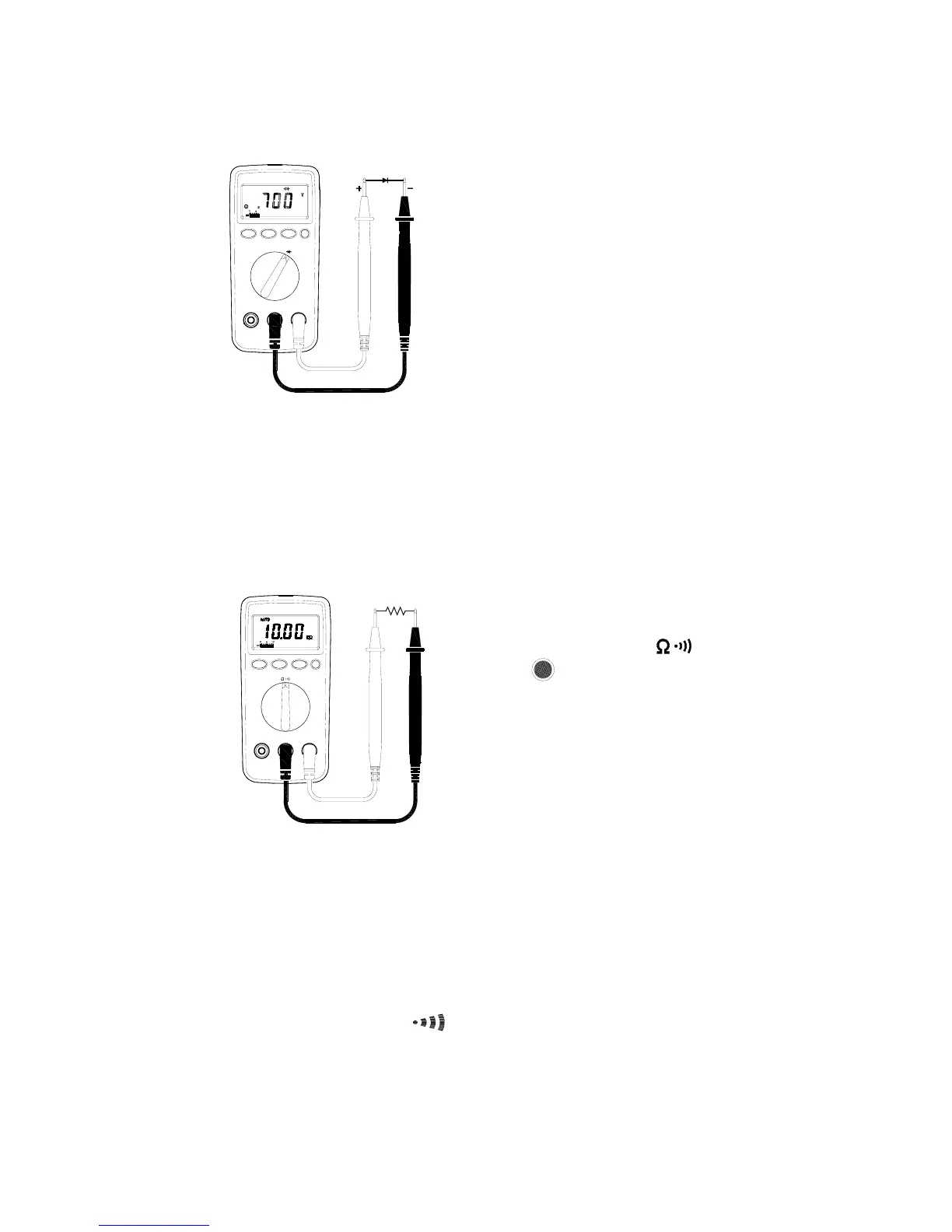
2-2-6 Resistance Measurements
WARNING!
Before taking any in-circuit measurement , remove power from
the circuit being tested and discharge all capacitors in the
circuit.
⊇ Connect red test lead to “ Ω ”jack and
black test lead to “COM ”jack.
⊄ Set Range Switch to “ ” range
and press button to “Ω”function.
⊂ Connect test lead to the circuit being
measured and read the resistance value
on LCD.
2-2-7 Continuity Measurements
WARNING!
Before taking any in-circuit measurement ,remove power from
the circuit being tested and discharge all capacitors in the
circuit.
⊇ Connect red test lead to “Ω”jack and black test lead to “COM ” jack.
⊄ Set Range Switch to “
” range , by pressing button.