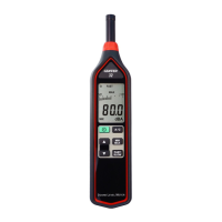
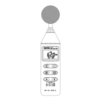
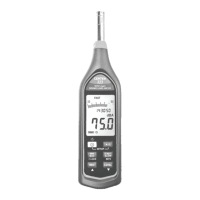
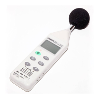
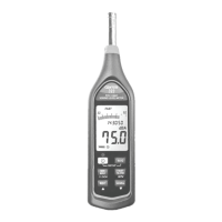
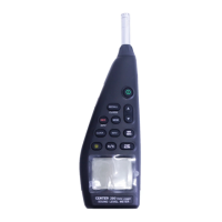
DATA LOGGER SOUND LEVEL METER
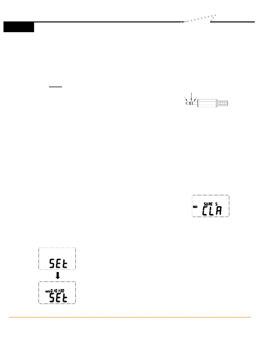
DC Signal
AC Signal Ground
○
12
Signal output terminal
AC: 1 Vrms Corresponding to each range step.
Output impedance ≒ 100Ω
Output signal by standard 3.5mm coaxial socket signal on pin.
Note: At “Auto” level range, output signal is Auto select on “Lo” or “Med”
or “Hi” level range.
DC: Output : 10mV/dB
Output impedance ≒ 1KΩ
Output signal by standard 3.5mm coaxial socket signal on middle.
○
13
External DC 9V power supply terminal
For connection with AC adapter.
○
14
Tripod mounting screw.
○
15
Battery Cover
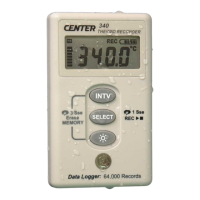
V. DATA LOGGER CLOCK & INTERVAL SETUP
▪ DataLogger:
When one presses the "REC" button, the meter will
start recording, and pressing the "REC" button again
will stop recording, If you want to clear the memory,
power off the meter, then press and hold “REC” button
and then press power button and hold at least 5
seconds, then LCD will show "CLR" and “SURE” to
clear the memory.
▪ Clock Setup :
1: press and hold “A/C” button and then power on the
meter:
2: press “MAX MIN”(clock) button:
3: press "REC" ▲ or "LEVEL" ▼ to increase or decrease
number, press “MAX MIN”(clock) to adjust next item. The
adjusting order is year→ month→ day→ hour→ minute,
then press “MAX MIN” (clock) to finish adjusting. If you
want abort during a setup process, press power button to
cancel.
2
www.SpectoTechnology.com
Specto Technology
y
1061 E. Elizabeth Ave. Linden, NJ 07036
y
866-925-7737
y
info@spectotechnology
6