Page 9For technical questions, please call 1-888-866-5797.ITEM 61454
SAFETYSETUPOPERATIONMAINTENANCE
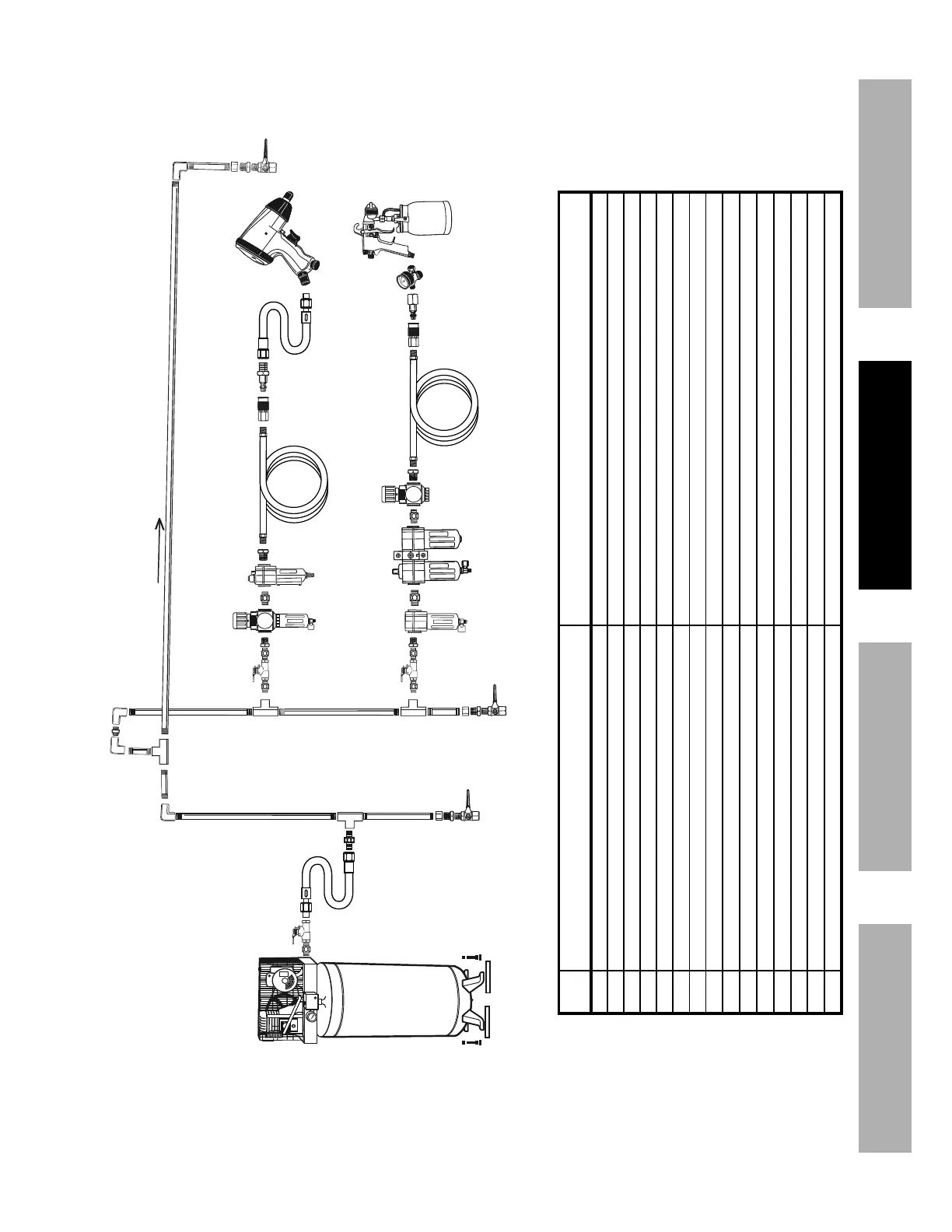
Figure H: Stationary Air Supply Setup
N
L
L O
M
C
C
Non-lubricated
A
C
D
Description Function
A Vibration Pads For noise and vibration reduction
B Anchor Bolts Secures air compressor in place
C Ball Valve Isolates sections of system for maintenance
D Isolation Hose For vibration reduction
E Main Air Line - 3/4″ minimum recommended Distributes air to branch lines
F Ball Valve To drain moisture from system
G Branch Air Line -1/2″ minimum recommended Brings air to point of use
H Air Hose Connects air to tool
I Filter Prevents dirt and condensation from damaging tool or workpiece
J Regulator Adjusts air pressure to tool
K Lubricator (optional) For air tool lubrication
L Coupler and Plug Provides quick connection and release
M Leader Hose (optional) Increases coupler life
N Air Cleaner / Dryer (optional) Prevents water vapor from damaging workpiece
O Air Adjusting Valve (optional) For fine tuning airflow at tool