SKU 94667 For technical questions, please call 1-800-444-3353.
PAGE 9
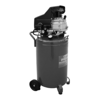
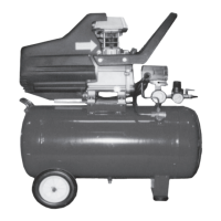
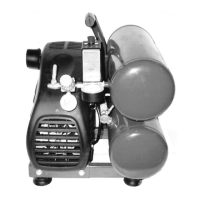
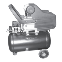
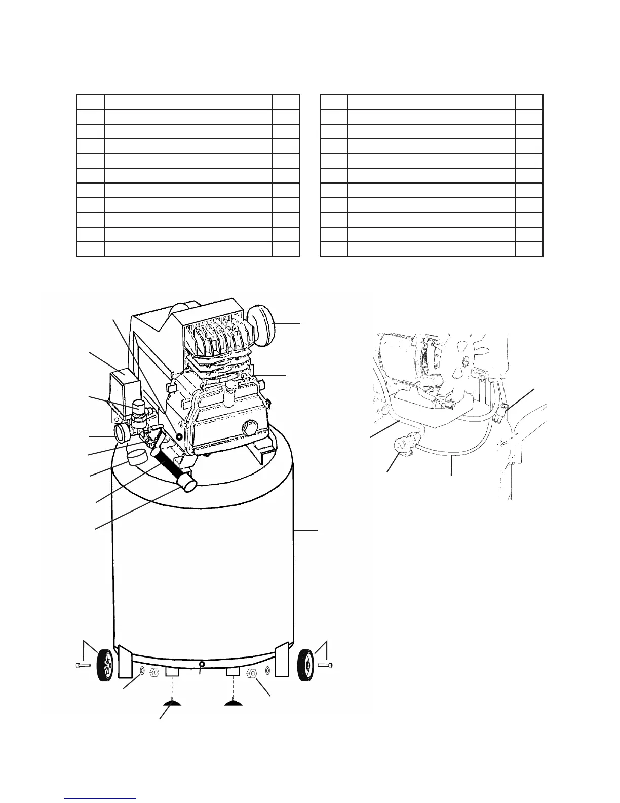
PARTS LIST A / ASSEMBLY DIAGRAM A
Part Description Qty.
1A ON/OFF Power Switch 1
2A Tool Pressure Adjuster 1
3A Tank Pressure Gauge 1
4A Tool Pressure Gauge 1
5A Pressure Release Valve 1
6A Air Flow Valve 1
7A Air Filter 1
8A Air Flow Lid 1
9A Air Tank 1
10A Water Drain Valve 1
Part Description Qty.
11A Quick Release Coupler 1
12A Rubber Wheel with Bolt 2
13A Washer 2
14A Nut 2
15A Fitting 1
16A Oil Drain Plug with Gasket 1
17A Foot 2
18A Unloader Valve 1
19A Polyurethane Unloader Tube 1
20A Copper Air Tube 1
REV 07b; 07f; 10d
1A
2A
4A
5A
7A
8A
9A
10A
12A
13A
14A
15A
11A
16A
17A
18A
19A
20A
(Rear View with motor cover removed.)
3A
6A
12A