13
Installation Wiring Diagram
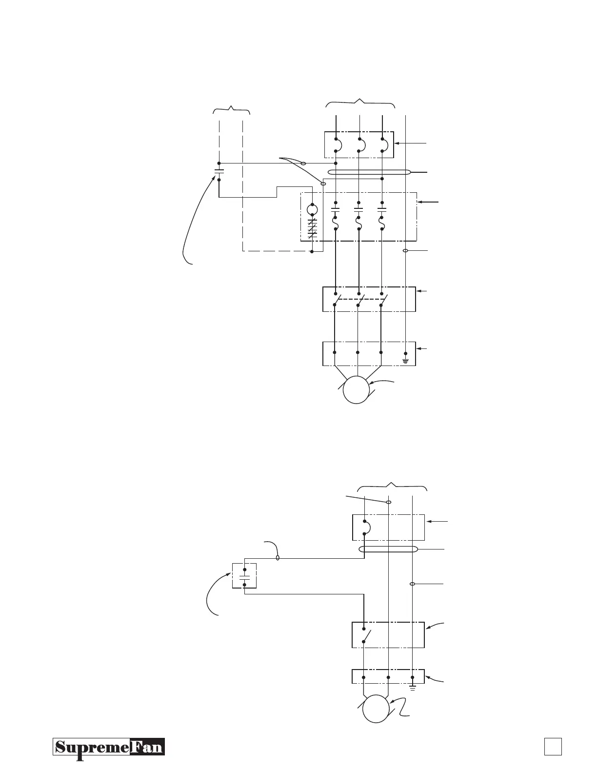
Installation Wiring Diagram 120V, 1 Phase
HN
c
L
1
L
2
L
3
GND.
Control Source May
Be Line Voltage or
120V., Controlled Via
Interlocking Aux. Contact,
Relay Switch or Time
Clock Contact
Alternate
Control Source
120V., 1 Phase
208 – 230/460V. 3O
Circuit Breaker
Field Furnished
& Installed
Conduit & Conductors
Field Furnished &
Installed - See Note 1
Magnetic Motor
Starter w/Thermal
Overloads - Fields
Furnished & Installed
See Note 2
Green Ground Wire,
Size Per NEC as follows:
15A-#14 (Min. Size)
20A-#12, 40A-#10
Optional Factory Furnished
& Installed or Field Furnished
& Installed Manual Motor
Disconnect Switch
Integral Connection
J-Box on Motor
Supply Fan Motor – See
Wiring Diagram on Motor
For Correct Connection
Configuration
Note:
1. Conductors – UL listed 600V, 105° C copper stranded.
Size conductors per NEC at 125% of motor full load amps
(#14 AWG. Min.). Size conduit per NEC for size & number of
conductors.
2. If motor is provided with thermal overloads, overloads may be
omitted in the magnetic starter.
3. All material & components must be UL or ETL listed or recognized.
4. To verify correct fan rotation, momentarily energize motor. If rotation
is incorrect, (for 3 phase), reverse any two incoming line conductors,
(for 1 phase), interchange conductors 5&8. See wiring diagram on
motor.
Note:
For 208-230/460V.
Single Phase Motors,
Delete Line 1.3 and
Associated Components
Delete if
Alternate
Control Source
Used
HN
GND.
Note-1:
1. Conductors – UL listed 600V, 105° C copper stranded. Size
conductors per NEC at 125% of motor full load amps (#14 AWG. Min.).
Size conduit per NEC for size & number of conductors.
2. All material & components must be UL or ETL listed or recognized.
To verify correct fan rotation, momentarily energize motor. If rotation is
incorrect, interchange conductors 5 & 8. See wiring diagram on motors.
White (Neutral)
120 V. 1 Phase
Circuit Breaker Field
Furnished and Installed
Conduit & Conductors Field
Furnished & Installed
See Note 1
Green Ground Wire,
Size Per NEC as Follows:
15A-14# (Min. Size), 40A #10
Optional Factory Furnished &
Installed or Field Furnished &
Installed Manual Motor
Disconnect Switch
Integral Connection
J-Box on Motor
Control Source may be Line
Voltage or 120V., Controlled Via
Interlocking Aux., Contact,
Relay Contact, Remote SPST
Switch or Time Clock Contact
Black, Red, Blue
(or any Color Except
Green or White)
Supply Fan Motor – See Wiring Diagram
on Motor for Correct Connection Configuration