14
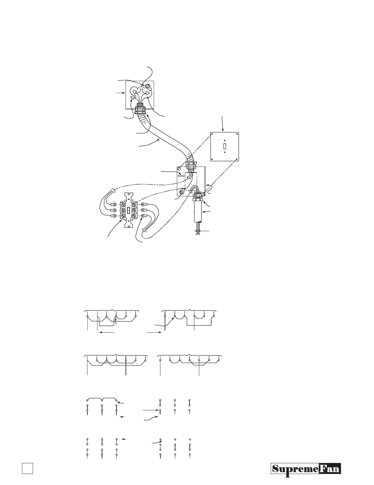
Optional Disconnect Switch, Conduit & Wiring
Installation
(3 Phase Shown, 1 Phase Similar)
Wiring Diagrams / Baldor Motors Conductor
Connections at Motor Integral Junction Box
NOTE:
1- All component parts shall be ETL or UL listed or classified.
2- Conduit & fitting sizes shall be per the NEC (Nat’l, Elec. Code)
3- The conductors shall be sized for 125% of the full load amps the
motor being used per the NEC (#14 AWG. minimum)
4- Ground the motor case per the NEC as follows: 15A= #14,
20A= #12, 40A= #10.
Motor Leads – See Motor
Wiring Diagram
Grounding Screw
on Motor Case
Integral Connection
J-Box on Motor
Pressure Type
Wire Connectors
Green Ground
Conductor
4" Square Weatherproof
Cover for (1) Toggle Switch
4" Square 2 1/8" Deep
Weatherproof Outlet Box
W.P. Conduit Connector
Rigid Conduit
600 V., 105° C Copper
Stranded Conductors Min. #14
AWG. Typical (Field Installed)
Closed Ring or Upturn Fork
Crimp on Wire Terminals-TYP.
2 Pole (1 Phase) or 3 Pole
(3 Phase) 115-20r/230-160 V.
Manual Motor Disconnect Switch
Min. Spacing Between Switch
Terminals & Dead Metal Parts
0 - 250 V.-1/4", 251-460V.-1/2"
Sealtite Conduit Connector
Fitting (Typical 2 Places)
Sealtite Conduit
H
HN
N
123458 123458
L
1
L
2
L
1
L
1
L
2
L
3
L
1
L
2
L
3
L
1
L
2
L
3
L
2
123J4
54
4
7
1
5
5
8
2
6
9
3
6
879
213
10 11 12
L
1
L
2
L
3
4
7
1
5
8
2
6
9
3
10 11 12
546
879
213
8123J458
1 Phase, Dual Voltage – Without Thermal Overload
1 Phase, Dual Voltage – With Thermal Overload
3 Phase, Dual Voltage – Without Thermal Overloads
3 Phase, Dual Voltage – With Thermal Overloads
Low Voltage (115V) Conductors to Motors
Low Voltage (115V) Conductors to Motors
High Voltage (208-230V) Conductors to Motors
High Voltage (208-230V) Conductors to Motors
Low Voltage (208-230V) High Voltage (460V)
Low Voltage (208-230V) High Voltage (460V)
Note:
To Reverse 1 Phase Rotation,
Either Voltage, Interchange
Conductors 5 & 8
Note:
To Reverse 3 Phase Rotation,
Either Voltage, Reverse any Two
Incoming Line Conductor Connections
Warning:
Verify Wiring Diagram on Motor
(For Variations) Prior to Connecting
or Energizing Motor.
Motor Conductor
Connections
(Typical)
UL Listed Compression
Type Wire Connectors (Typ.)
Motor Conductor
Designations
(Typical)
Incoming
Line (Typ)
Incoming Line (Typ)