3
Kitchen Hood Exhauster – Installation Procedure
Duct Construction
1. Ducts should be sized for a minimum air velocity of 1500 FPM and a maximum of 2200 FPM (consult local
codes).
2. Ducts shall be constructed of material not less than 16 gauge steel.
3. All joints and seams shall be made with a continuous grease tight weld on the external surface.
4. Ducts must have clean outs (consult local codes).
5. Ducts must be constructed to prevent accumulation of grease build-up.
6. No ducts shall be penetrated be screws, nails, etc.
7. Duct shaft should be built in accordance with local code and space requirements.
Curb
A minimum curb height of 8” is recommended (consult local codes). The curb must be level and square; refer to
physical dimensions for maximum curb size.
Electrical
Necessary electrical service must be brought to the unit near the motor location (consult local codes prior to installa-
tion).
Clearance
Proper clearance must be provided on the hinge side of the fan from any parapet or wall to allow fan to swing open
for duct cleaning. See dimension “E” in catalog dimensional data.
Step-1 Installation of Fan Base
Once the curb has been inspected for squareness and
level, the fan base should be set. Loosen hinge bolts
securing blower to base and lift blower off base. Set base
on roof curb. Verify fan base is oriented with hinge bolts
on correct side for desired direction of blower discharge.
Step-2 Installation of Duct and Transition
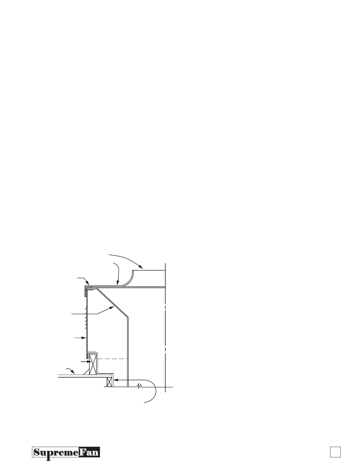
The all welded steel duct (by others) can now be set (see
Fig. 1). Drop prefabricated grease duct through opening
in base. Flanges on duct transition must set on lip of
base to hold duct in place. Do not terminate grease duct
below vented fan base.
NOTE: If the ductwork assembly is designed and installed as shown in Fig. 1,
no fasteners will be required to secure the fan base into place.
Factory 1
Installed
Gasket
ll Welded
Grease Duct
& Transition
To Set on Top
of Lip of Fan
Base
Vented
Fan Base
Curb
(by others)
Roof
1 Hour Min. Fire Wall
(Consult Local Codes
for Requirments & Space)
Fan Intake
Blower Assembly
Figure 1



 To Next Page