7
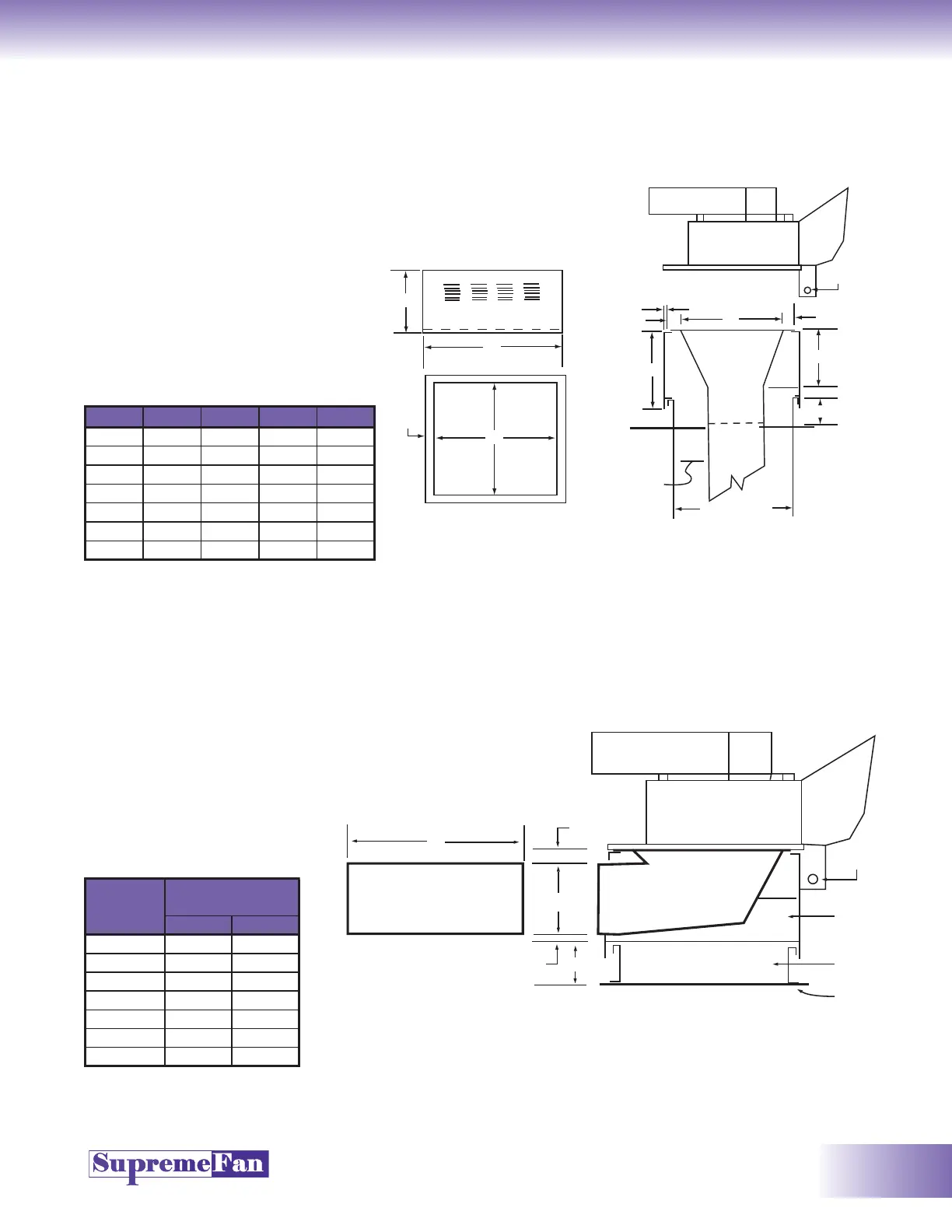
Grease Duct Installation
Side Inlet Fitting (Factory Option)
Grease Duct
Installation Procedure
1. Loosen hinge bolts
securing blower to base.
Lift blower off base. Set
base on roof curb.
2. Drop grease duct through
opening in base. Flanges on
duct will set on lip of base to
hold duct in place.
3. Set blower on base and
tighten bolts that secure
hinges to base.
MODEL A B C D
GBD-125
34 31 20 27
GBD-150
34 31 20 27
GBD-182
40 1/2 37 1/2 19 33 1/2
GBD-222
40 1/2 37 1/2 19 33 1/2
GBD-245
47 44 19 40
GBD-270
53 50 19 46
GBD-300
65 1/2 62 1/2 19 58 1/2
When Ordering...
1. Supply A and B dimensions
for proper connection of the
grease duct.
2. Supply C dimension that will
allow proper horizontal duct
run. Duct installation must
conform with NFPA 96 or
local code requirements.
Side View
C
Vented Base
A
1 1/2"
B
Plain View
Exhaust
Blower
Drain
1/2"
3"
D
3"
C
16"
Factory
Optional
Transition
Funnel
Fitting
Roof Line
Grease
Duct by
Others
8"
Clearance
Per Local
Code
Duct Shaft
Factory
Vented
Base
Factory
Optional
Roof Curb
B
3"
A
1/2"
Front View of
Duct Opening
C
Curb Height Will Vary Depending on
Length of Exposed Duct on Roof
Roof Line
Roof Curb
GBD Base
Side Duct
Inlet Fitting
Drain
Exhaust Blower
AB
GBD-125 14 30 1/2
GBD-150 14 30 1/2
GBD-182 14 36 3/8
GBD-222 14 36 3/8
GBD-245 14 43 1/2
GBD-270 14 49 1/2
GBD-300 14 61 7/8
MAXIMUM
DIMENSIONS
MODEL