EasyManua.ls Logo

Centrometal Cm Pelet-set - User Manual

Centrometal Cm Pelet-set
80 pages
Print Icon
To Next Page IconTo Next Page
Loading...
Tehnical instructions
HEATING TECHNIQUE
Centrometal d.o.o. - Glavna 12, 40306 Macinec, Croatia, tel: +385 40 372 600, fax: +385 40 372 61 1
Cm Pelet-set
REGULATION
THE FIRST START-UP MUST BE DONE BY AUTHORIZED PERSON
OTHERWISE PRODUCT WARRANTY IS NOT VALID
READY
TURPS- 10/2017-v1_20-ENG
80°C
120°C
0%
1700
15k
30%
60°C
70°C
50°C
55°C
Cm Pelet-set
Question and Answer IconNeed help?

Do you have a question about the Centrometal Cm Pelet-set and is the answer not in the manual?

Summary

Technical Instructions and Product Overview

Centrometal Company Information

Company address and contact details.

Control Panel Display

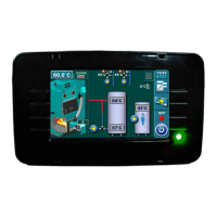
Shows the main interface of the device.

Important Safety Notice: First Start-up

Crucial safety warning about first start-up.

Initial Setup and Screen Navigation

Switching On and Language Selection

Describes the startup sequence and language choice.

Understanding the Initial Message Screen

Explains the default screen shown if language selection is off.

Touchscreen Operation Warning During Startup

Critical warning about touchscreen use during startup.

System Navigation and Controls

Main Menu Structure Overview

Overview of the main menu options and their icons.

Control Panel Buttons and Functions

Detailed description of each button's operation.

Control Panel Display Symbols

Symbol Key and Descriptions

Lists and explains the meaning of symbols on the screen.

Boiler Type Display Examples

Shows how different boiler types are represented.

Control Panel Symbols Explained

Thermostat and Heating Circuit Symbols

Explains symbols related to room thermostats and heating circuits.

Hot Water and External Control Symbols

Explains symbols for domestic hot water and external controls.

Wi-Fi Box and Cascade System Symbols

Explains symbols for connectivity and cascade setups.

Parameter Adjustment Introduction

Return Flow Protection Symbols

Symbols related to return flow protection.

Parameter Adjustment Menu Types

Overview of the four types of parameter adjustment menus.

Parameter Adjustment Procedures

Burner Fan RPM Adjustment Method

Method for adjusting burner fan speed.

DHW Sensor Type Selection Method

Method for setting the DHW sensor.

Additional Equipment Settings Method

Method for configuring additional equipment.

Power P2 Parameter Adjustment Method

Method for adjusting parameters on power P2.

Maintenance and Cleaning Procedures

Cleaning the Burner and Grate

Steps for cleaning the burner and its grate.

Burner Fan RPM for Cleaning

Setting fan speed during cleaning.

Temperature and Scheduling Settings

Temperature Menu Options

Overview of temperature-related settings.

Boiler and Schedule Configuration

Setting schedules for boiler operation.

Schedule Tables and Event History

Setting Schedule Tables

How to set up daily heating schedules.

Viewing Error and Warning History

Accessing logs of system errors and warnings.

System Operation Modes

General Operation Menu

Overview of the operation menu.

Forced Shutdown Procedure

How to safely shut down the burner.

Manual Test Functions

Using manual tests to check components.

Pellet System Operations

Pellet Conveyor Filling

Initial filling and refilling of the pellet conveyor.

Weighing Check Function

Checking pellet delivery accuracy.

Saving and Loading Settings

Managing system configurations.

Standard Equipment Configuration

Sensor Type Settings

Configuring boiler and circuit sensors.

Photocell Parameter Adjustment

Adjusting photocell settings.

Mixing Heating Circuit Setup

Configuring heating circuits.

Heating Circuit Details

Viewing Heating Circuit Parameters

Accessing and understanding circuit information.

Heating Circuit Customization Options

Options for including/excluding circuits and modes.

Heating Circuit Parameter Settings

Enabling;Disabling Heating Circuits

Activating or deactivating specific heating circuits.

Setting Heating Curve Values

Adjusting the heating curve for optimal performance.

Adjusting Correction Coefficients

Fine-tuning circuit parameters.

Advanced Heating Circuit Settings

Setting Day Room Temperature

Adjusting temperature for daytime.

Setting Night Room Temperature

Adjusting temperature for nighttime.

Configuring Day;Night Modes and Schedules

Setting working modes and schedules.

Additional Features and Modes

Setting Additional Equipment

Enabling and configuring extra components.

Freeze Guard Functionality

Protecting the system from freezing.

Selecting Working Modes

Choosing between Winter, Summer, or Auto modes.

Burner Operation Settings

Time to Burner Extinguishing

Setting the shutdown time for the burner.

Burner Modulation Configuration

Adjusting burner modulation parameters.

Display Settings and Options

Customizing the control panel display.

System Information and Special Modes

System Information Display

Accessing statistics and software versions.

Pellet Delivery Correction

Adjusting pellet delivery steps.

Chimney Sweeper Mode

Using the system for flue gas measurement.

Installation and Burner Stages

Accessing Installation Menu (PIN)

How to enter the service installation menu.

Understanding Burner Working Stages

Explanation of different burner operating states.

System Configurations

Configuration A-0-0: Boiler + Accumulation Tank

Basic setup with boiler and accumulation tank.

Configuration A-1-0: Boiler + Accumulation + DHW

Setup with boiler, accumulation tank, and DHW.

Configuration B-2-1: EKO-CKB P with Dual Heating + DHW

EKO-CKB P with dual heating and DHW.

Internet Connectivity and Supervision

Internet Supervision Setup

Connecting the regulation to the internet via WiFi.

WiFi Network Configuration

Setting up WiFi network name and password.

Important Notes for Internet Setup

Key requirements and tips for connectivity.

Electrical Schematics

Electric Scheme 1;6: Power Supply and Outputs

Diagram showing power supply, main switch, and outputs.

Electric Scheme 2;6: Mixing Valves

Diagram showing mixing valve actuators.

Electric Scheme 3;6: Inputs and Sensors

Diagram detailing inputs, sensors, and room correctors.

Electric Scheme 4;6: Display Connections

Diagram showing connections for the TFT display.

Electric Scheme 5;6: Burner CPPL 14-50 KW

Diagram for the burner components.

Electric Scheme 6;6: Burner CPPL 90 KW

Diagram for the burner components.

Centrometal Cm Pelet-set Specifications

General IconGeneral
BrandCentrometal
ModelCm Pelet-set
CategoryControl Panel
LanguageEnglish