OPTIONS AND FEATURES
19. Learn Button
The Learn button (Fig 11) is located on the rear cover of the AGDO and serves to initiate the functions as
described in the following table;
Function Action Reference
Learn Hand Transmitter Codes Momentary press Sec.15
Delete Hand Transmitter Codes Press and hold while powering-up Sec.15
Entering SOF Adjustment Mode Press and hold for 2 sec. Sec.14
20. LED Indicator
The LED Indicator (Fig 11) is located on the rear cover of the AGDO and serves to provide visual
indication of functionality sequences as described in the following table;
Display Indicator
Glow Solid Reached door closed position
Slow Flash Reached door open position
Medium Flash Learning or deleting Hand Transmitter codes
Quick Flash Force adjust mode activated
None AGDO is traveling between open and closed positions
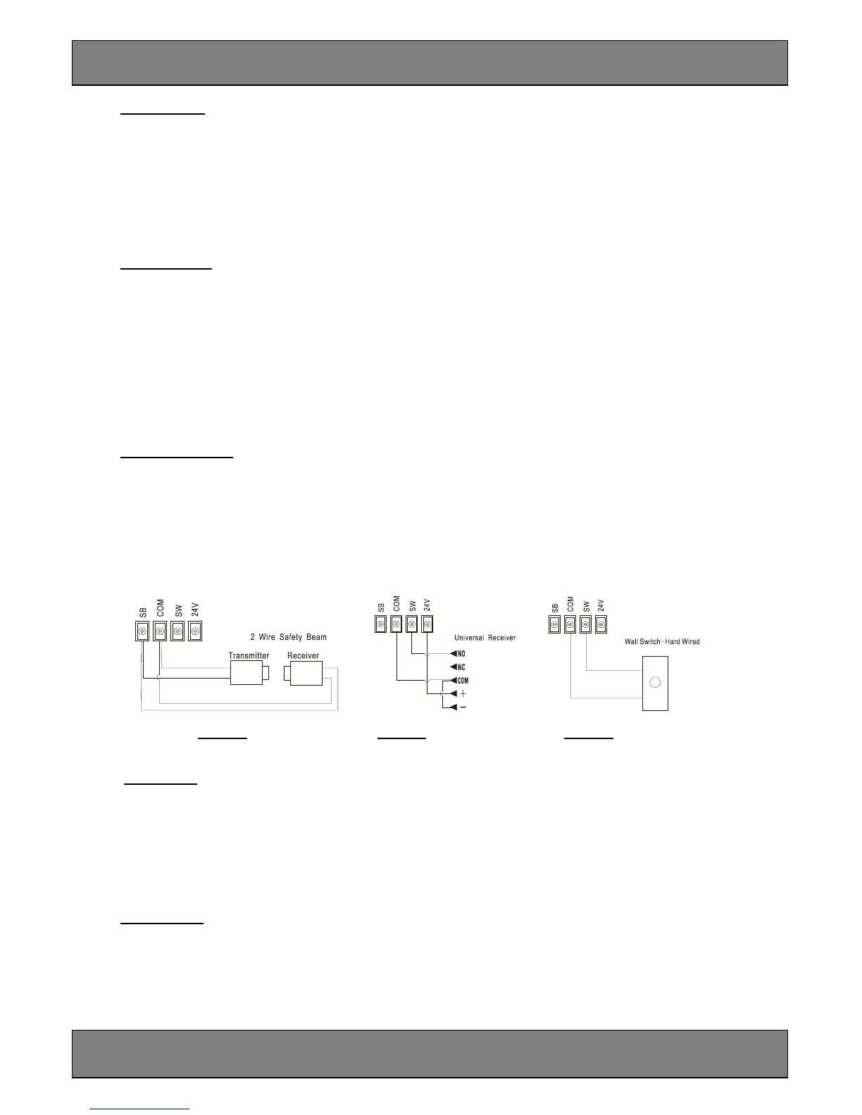
21. Output Terminals
4 Output Terminals (Fig.11) are provided within the back cover of the AGDO to support the connection
of the following accessories;
a. Genuine 2 wire Safety Beams (Fig 12A)
b. 24VDC universal receiver (Fig 12B)
c. Normally open momentary contact Wall Switch (Fig 12)
Fig 12A Fig 12B Fig 12C
22. Run Button
The Run button (Fig.11) is located on the rear cover of the AGDO and serves to initiate the following
functions;
Function Action
Activate AGDO Momentary press
Safety Beam override Press and hold until garage door is fully closed
23. Safety Beams
Genuine 2 wire Safety Beams may be connected to the AGDO.
The installation of Safety Beams greatly enhances safety by constantly monitoring for persons or objects
that might pass within the path of the moving garage door. The AGDO will commence to safety reverse if
the Safety Beams become momentarily or permanently interrupted while the garage door is closing.