# "!
H
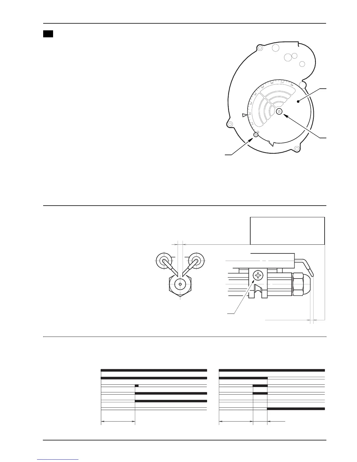
$ AIR DAMPER ADJUSTMENT
M<1$5170,+*-.($$.@$$*<1$+-5T5+*1$-)$3+21$NA$+2k0)*-(7$*<1$+-5
2+3815$$%9&/$+@*15$,..)-(7$*<1$)451;)$$% &S
M<1$)1**-(7)$-(2-4+*12$-($*<1$)4<120,1$51@15$*.$*<1$N05(15
;-*<$-*)$31*+,$4.C15$@-**12$+(2$*<1$4.3N0)*-.($4<+3N15$;-*<
m_15.n$21851))-.(S
These regulations are purely indicative. Each installation how-
ever, has its own unpredictable working conditions: actual
nozzle output; positive or negative pressure in the combus-
tion-chamber, the need of excess air, etc.
All these conditions may require a different air-damper set-
ting.
It is important to take account of the fact that the air
output of the fan differs according to whether the burn-
er has its metal cover fitted or not.
Therefore we recommended to proceed as follows:
U$ +2k0)*$*<1$+-5$2+3815$+)$-(2-4+*12$-($*<1$)4<120,1$%#&f
U$ 3.0(*$*<1$4.C15/$)-38,A$NA$31+()$.@$*<1$08815$)451;f
U$ 4<14?$)3.?1$(03N15f
U$ )<.0,2$-*$N14.31$(141))+5A$*.$3.2-@A$*<1$+-5$.0*80*/$513.C1$*<1$4.C15$NA$,..)1(-(7$*<1$)451;/
+2k0)*$*<1$+-5$2+3815/$513.0(*$*<1$4.C15$+(2$@-(+,,A$514<14?$*<1$)3.?1$(03N15S
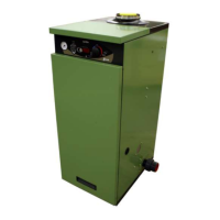
ELECTRODE SETTING
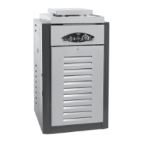
BURNER START-UP CYCLE
2
1
2
BRHKR
3
Attention:
:1@.51$+))13N,-(7$.5$513.C-(7$*<1
(.__,1/$,..)1 ($ *<1$)451;$ (A)$+( 2
3.C1$*<1$1,14*5.21)$+<1+2S
2 – 2.5 mm
4 [$0.3 mm
IMPORTANT:
THESE DIMENSIONS
MUST BE OBSERVED
BR #"
A
Q.53+, I.4?T.0*/$201$*.$,-7<*T@+-,051
M<153.)*+*
E.*.5
'7(-*-.($*5+()@.5315
J+,C1
W,+31
I.4?T.0*$,+38
]$12s
BR !
]$12s
]$5s