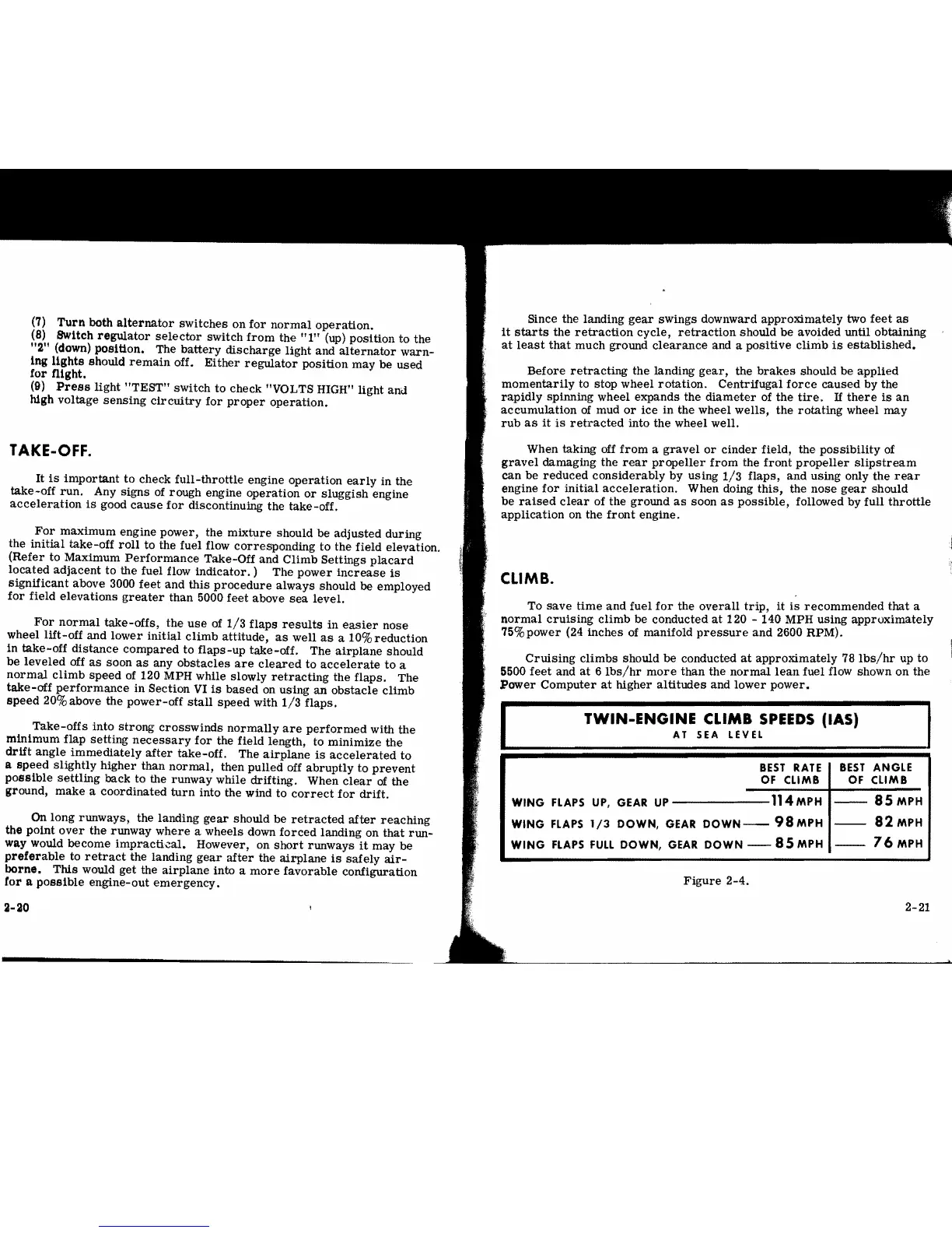
(7)
Turn
both
alternator
switches
on
for
normal
operation.
(8)
SWitch
regulator
selector
switch
from
the
"I"
(up)
position
to the
"2"
(down) position. The
battery
discharge
light and
alternator
warn-
ing
lights
should
remain
off.
Either
regulator
position
may be used
tor
filght.
(9)
Press
light
"TEST"
sWitch
to
check "VOLTS HIGH" light and
high voltage
sensing
circultry
for
proper
operation.
TAKE-OFF.
It
is
important
to
check
full-throttle
engine
operation
early
in the
take-off
run.
Any
signs
of rough engine
operation
or
sluggish
engine
acceleration
is
good
cause
for
discontinuing
the
take-off.
For
maximum
engine power, the
mixture
should be
adjusted
during
the
initial
take-off
roll
to
the fuel flow
corresponding
to
the field elevation.
(Refer
to Maximum
Performance
Take-Off and
Climb
Settings
placard
located
adjacent
to
the fuel flow
indicator.
) The
power
increase
is
significant
above 3000
feet
and
this
procedure
always should be employed
for
field
elevations
greater
than 5000
feet
above
sea
level.
For
normal
take-offs,
the
use
of
1/3
flaps
results
in
easier
nose
wheel lift-off and lower initial
climb
attitude,
as
well
as
a 10% reduction
in
take-off
distance
compared
to
flaps-up
take-of£. The
airplane
should
be
leveled
off
as
soon
as
any
obstacles
are
cleared
to
accelerate
to
a
normal
climb
speed
of
120 MPH while slowly
retracting
the flaps. The
take-off
performance
in Section
VI
is
based
on using
an
obstacle
climb
speed
20% above the
power-off
stall
speed
with
1/3
flaps.
Take-offs
into
strong
crOSSWinds
normally
are
performed
with
the
minimum flap
setting
necessary
for
the field length, to
minimize
the
drift
angle
immediately
after
take-off. The
airplane
is
accelerated
to
a
speed
slightly
higher
than
normal,
then
pulled
off
abruptly
to
prevent
possible
settling
back to the runway while drifting. When
clear
of
the
ground, make a coordinated
turn
into the wind to
correct
for
drift.
On
long runways, the landing
gear
should be
retracted
after
reaching
the pOint
over
the runway
where
a wheels down
forced
landing on
that
run-
way would become impracti.::al. However, on
short
runways
it
may be
preferable
to
retract
the landing
gear
after
the
airplane
is
safely
air-
borne.
This
would get the
airplane
into a
more
favorable
configuration
tor
a
possible
engine-out
emergency.
Since the landing
gear
swings downward apprOximately two
feet
as
it
starts
the
retraction
cycle,
retraction
should be avoided until obtaining
at
least
that
much ground
clearance
and a
positive
climb
is
established.
Before
retracting
the
landing
gear.
the
brakes
should be applied
momentarily
to stop wheel
rotation.
Centrifugal
force
caused
by the
rapidly
spinning wheel expands the
diameter
of the
tire.
If
there
is
an
accumulation
of
mud
or
ice
in the wheel
wells,
the
rotating
wheel
may
rub
as
it
is
retracted
into the wheel well.
When taking off
from
a
gravel
or
cinder
field, the
possibility
of
gravel
damaging the
rear
propeller
from
the
front
propeller
Slipstream
can
be
reduced
conSiderably by using
1/3
flaps,
and
using only the
rear
engine
for
initial
acceleration.
When doing
this,
the
nose
gear
should
be
raised
clear
of the ground
as
soon
as
possible,
followed by
full
throttle
application on the
front
engine.
CLIMB.
To
save
time
and
fuel
for
the
overall
trip,
it
is
recommended
that
a
normal
cruising
climb
be conducted
at
120 - 140 MPH using
approximately
75%power (24 inches of manifold
pressure
and
2600 RPM).
CruiSing
climbs
should be conducted
at
apprOximately 78
lbs/hr
up to
5500
feet
and
at
6
lbs/hr
more
than
the
normal
lean
fuel flow shown
on
the
Power
Computer
at
higher
altitudes
and
lower
power.
TWIN-ENGINE
CLIMB
SPEEDS
(lAS)
AT SEA
LEVEL
BEST
ANGLE
OF
CLIMB
BEST
RATE
OF
CLIMB
--
85MPH
WING
FLAPS
UP,
GEAR
UP
114MPH
--
82MPH
WING
FLAPS
1/3
DOWN,
GEAR
DOWN-
98MPH
WING
FLAPS
FULL
DOWN,
GEAR
DOWN
-
85
MPH
--
76MPH
Figure
2-4.
2-20
2-21
i



 To Next Page