General Installation
Vibrex 2000 and Vibrex 2000 Plus User Guide 49
Channel Descriptions -
The following table shows each channel,
identified by its appropriate label on the Vibrex unit, along with a
description of the channel’s identification and general function.
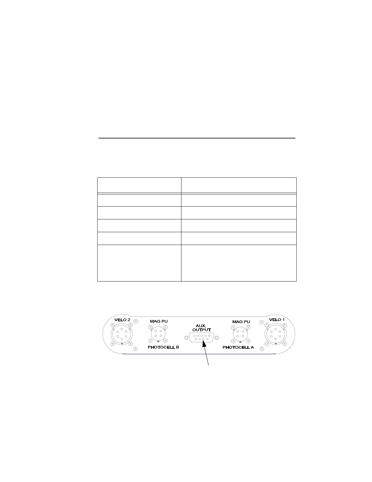
Connector Description -
The diagram below shows an illustration of
the connector subpanel.
Channel Description
VELO 1 Velocimeter channel No. 1
VELO 2 Velocimeter channel No. 2
MAG PU / PHOTOCELL A Photocell or magnetic pickup channel A
MAG PU / PHOTOCELL B Photocell or magnetic pickup channel B
AUX OUTPUT Auxiliary output for a nine-pin RS-232
serial cable; for interfacing the unit with
a personal computer (PC), a printer, or
the Strobex
PC OR PRINTER INTERFACE OR
STROBEX SYNCHRONIZATION OUT PULSE