82 Chadwick-Helmuth Company, Inc.
Chapter 5 - General Operation
• The closer the actual weight is to the specified amount and the closer
to the specified location, the better the initial and subsequent
solutions normally work.
• If the user performed the original solution exactly as specified, or if
the user input the actual propeller weight, the next solution will be
correct for the propeller.
CAUTION: Even with the Autocorrection feature off, the user must
record the actual weight and installation angles used.
5.4.3.2 Using the Propeller Protractor
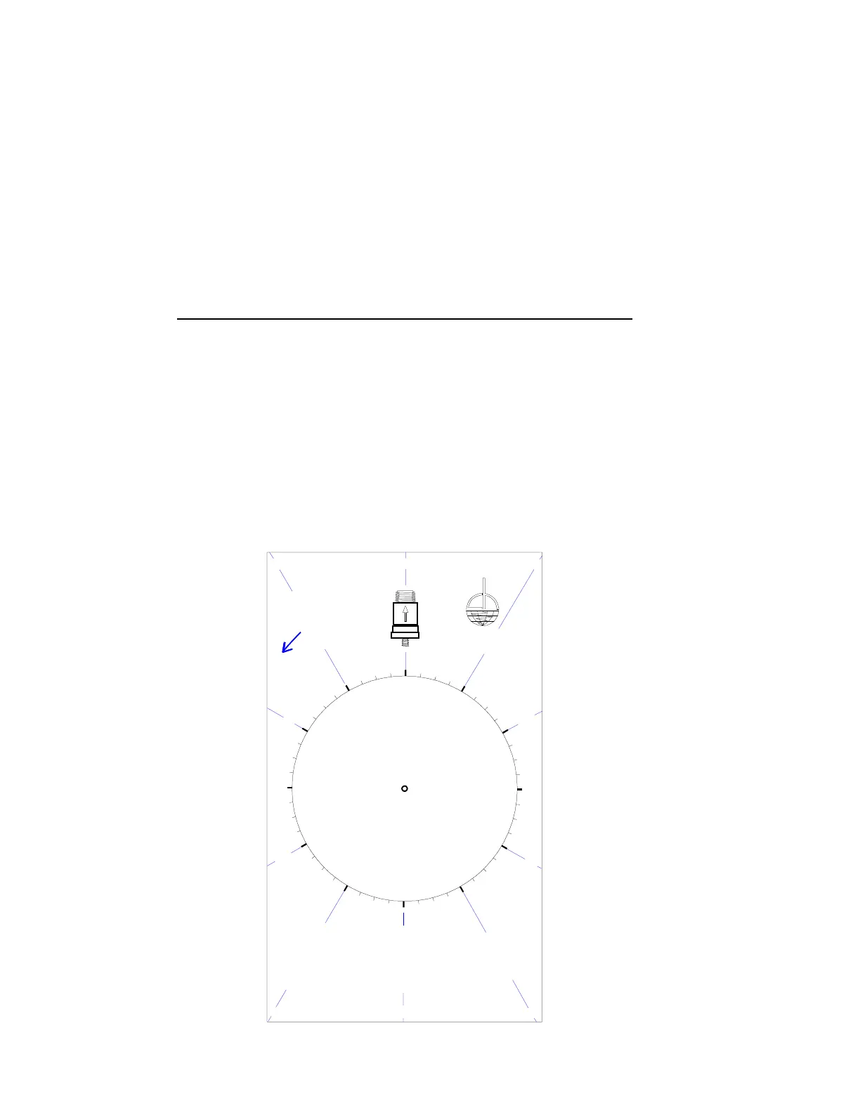
The illustration below shows a diagram of the Propeller Protractor.
3. ALIGN ARROW ON PROTRACTOR VELOCIMETER WITH ARROW ON PROP
2. ALIGN PHOTOCELL BEAM AND RETROREFLECTIVE TARGET.
1. USE SIDE OF PROTRACTOR WITH SAME DIRECTION OF ROTATION AS PROPELLER
4. ADD WEIGHT TO ANGLE ON PROP AS SPECIFIED BY BALANCER SOLUTION
VELOCIMETER BODY SO ARROWS ARE PARRALLEL AND IN THE SAME
:
4
5
C
H
A
D
W
I
C
K
H
E
L
M
U
T
H
C
O
I
N
C
.
(
8
1
8
)
5
7
5
-
6
1
6
1
I
N
S
T
R
U
C
T
I
O
N
S
AND ANGLE ON PROTRACTOR.
5
:
0
0
DIRECTION.
6
:
0
0
:
4
5
:
1
5
:30
:
3
0
4
:
0
0
:
4
5
:
1
5
:
1
5
:
3
0
:
4
5
:
3
0
:
1
5
:
1
5
3
:
0
0
:
3
0
:
4
5
:
1
5
2
:
0
0
:
4
5
:
3
0
:
4
5
:
3
0
:
1
5
:
3
0
:
4
5
CLOCKWISE
(CCW)
COUNTER
1
:
0
0
1
2
:
0
0
7
:
0
0
:
4
5
8
:
0
0
:
3
0
:
1
5
:
3
0
:
1
5
:
4
5
:
3
0
:
1
5
9
:
0
0
:
4
5
:
4
5
:
1
5
:30
1
0
:
0
0
:
1
5
P
R
O
T
R
A
C
T
O
R
P
/
N
1
3
0
5
3
1
1
:
0
0