EasyManuals Logo

CHAFFOTEAUX NIAGARA C 25 CF Installation And Servicing Instructions

CHAFFOTEAUX NIAGARA C 25 CF
To Next Page IconTo Next Page
To Previous Page IconTo Previous Page
Page #37 background imageLoading...
Page #37 background image
Warning
37
Product description
GB
Overall view
AB CD E
Water circuit diagram
0,0
0,5
1,0
1,5
2,0
2,5
3,0
3,5
4,0
4,5
5,0
0
100
200 300 400
500 600 700 800
900
1000
1100 1200 1300
mCE
l/h
Pression disponible
18-24 kW
30 kW
35 kW
Available pressure
A. Central Heating Flow
B. Domestic Hot Water Outlet
C. Gas Inlet
D. Domestic Cold Water Inlet
E. Central Heating Return
1. ue connector
2.
smoke sensor
3.
smoke hood
4. primary heat exchanger
5.
overheat sensor
6. C.H. Flow temperature probe
7. burner
8. ignition electrodes
9. gas valve
10. ignitor
11. secondary heat exchanger
12. C.H. pressure relief valve
13. D.H.W temperature probe
14.
domestic hot water circulating pump
15.
electrical connection box
16. C.H circuit lter
17. D.H.W ow switch
18. circulation pump with air release valve
19. domestic hot water valve
20. diverter valve
21. detection electrode
22. combustion chamber
23. C.H. return temperature probe
24. expansion heating chamber
27. domestic hot water tank
28.
tank sensor
29. expansion DHW chamber
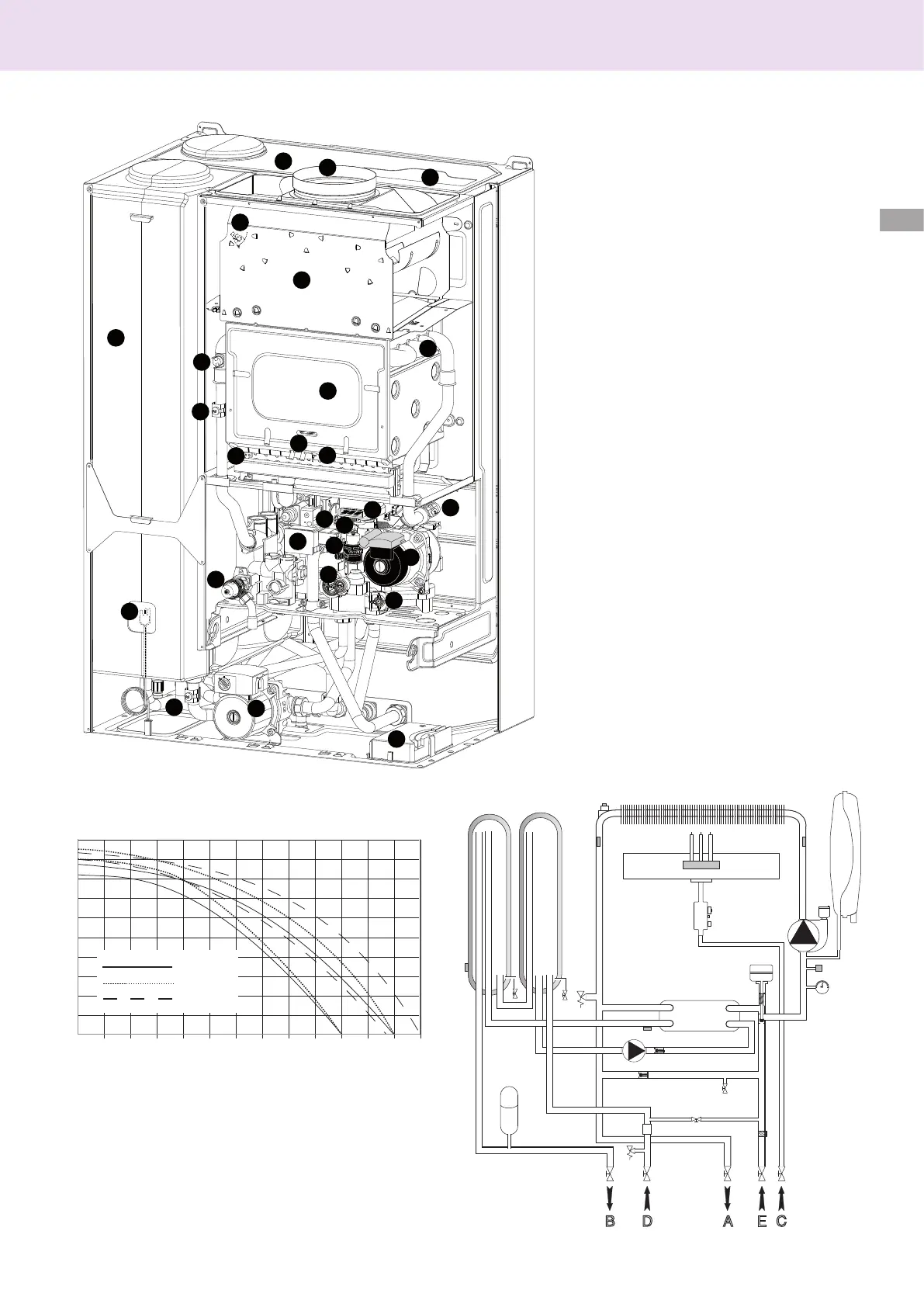
1
2
3
4
5
6
7
8
9
10
11
12
13
14
15
16
17
18
19
20
21
22
23
24
28
27
29

Table of Contents

Other manuals for CHAFFOTEAUX NIAGARA C 25 CF

Questions and Answers:

Question and Answer IconNeed help?

Do you have a question about the CHAFFOTEAUX NIAGARA C 25 CF and is the answer not in the manual?

CHAFFOTEAUX NIAGARA C 25 CF Specifications

General IconGeneral
BrandCHAFFOTEAUX
ModelNIAGARA C 25 CF
CategoryBoiler
LanguageEnglish

Related product manuals