EasyManuals Logo

CHAFFOTEAUX NIAGARA C 25 CF Installation And Servicing Instructions

CHAFFOTEAUX NIAGARA C 25 CF
To Next Page IconTo Next Page
To Previous Page IconTo Previous Page
Page #6 background imageLoading...
Page #6 background image
6
IT
Descrizione del prodotto
Vista complessiva
AB CD E
Schema idraulico
0,0
0,5
1,0
1,5
2,0
2,5
3,0
3,5
4,0
4,5
5,0
0
100
200 300 400
500 600 700 800
900
1000
1100 1200 1300
mCE
l/h
Pression disponible
18-24 kW
30 kW
35 kW
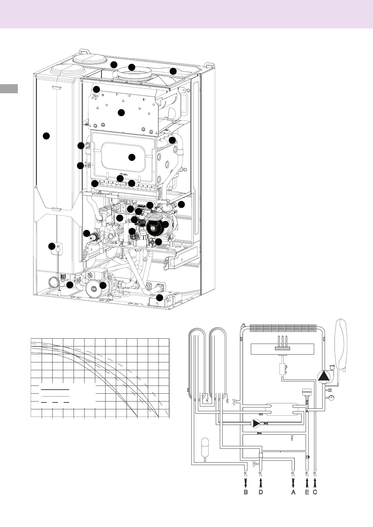
Pressione disponibile
A. Mandata impianto
B. Uscita acqua calda
C. Ingresso gas
D. Entrata acqua fredda
E. Ritorno impianto
1. Collettore scarico fumi
2. Termostato fumi
3. Cappa fumi
4. Scambiatore primario
5. Termostato di sovratemperatura
6. Sonda mandata riscaldamento
7. Bruciatore
8. Elettrodi di accensione
9. Valvola gas
10. Accenditore
11. Scambiatore secondario
12. Valvola di sicurezza riscaldamento
13. Sonda sanitario
14. Circolatore circuito sanitario
15. Collegamento periferiche
16. Filtro circuito riscaldamento
17. Flussimetro sanitario
18. Circolatore modulante con disareatore
circuito riscaldamento
19. Valvola di sicurezza sanitario
20. Valvola deviatrice motorizzata
21. Elettrodo di rilevazione amma
22. Camera di combustione
23. Sonda ritorno riscaldamento
24. Vaso espansione circuito riscaldamento
27. Bollitore
28. Sonda bollitore
29. Vaso espansione circuito sanitario
1
2
3
4
5
6
7
8
9
10
11
12
13
14
15
16
17
18
19
20
21
22
23
24
28
27
29
Descrizione del prodotto

Table of Contents

Other manuals for CHAFFOTEAUX NIAGARA C 25 CF

Questions and Answers:

Question and Answer IconNeed help?

Do you have a question about the CHAFFOTEAUX NIAGARA C 25 CF and is the answer not in the manual?

CHAFFOTEAUX NIAGARA C 25 CF Specifications

General IconGeneral
BrandCHAFFOTEAUX
ModelNIAGARA C 25 CF
CategoryBoiler
LanguageEnglish

Related product manuals