F.352-KO/EH-3C DRILL/AUG 03
1-2
1.0 INSTALLATION & SETUP
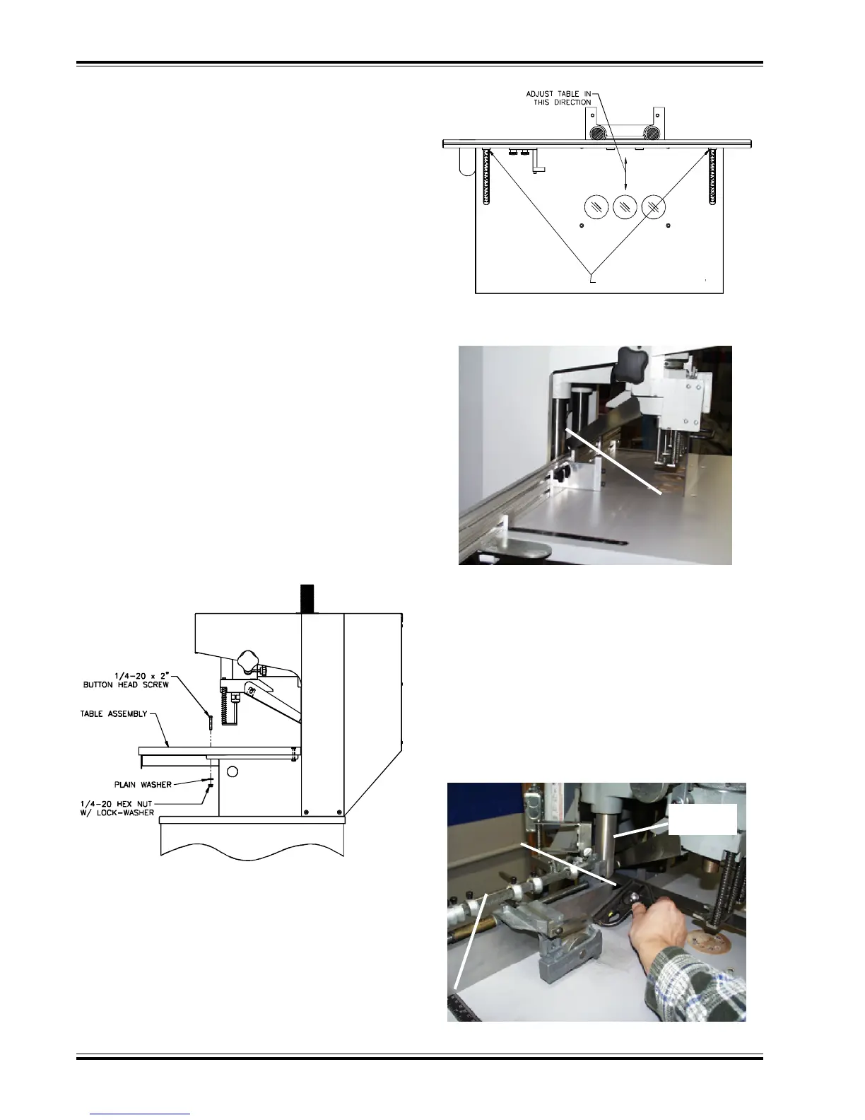
Using Auto-Trip Backgauge:
Attach the backgauge assembly to the table and set
both sides to the 6” position (as shown in fig. 1-5). Next,
position the table so that the front surface of the back-
gauge is 1-7/8” from the front of each pull down shaft
(see fig. 1-5). Now tighten the front two table-mounting
screws. Then move the backgauge forward and tighten
the rear two screws.
1.1 UNCRATING THE PAPER DRILL
This machine is shipped on a wooden skid and is en-
closed with a protective corrugated cover. It is held
onto the skid with plastic straps. Remove the straps
and carefully cut the corrugated cover down the side
and unwrap it from around the machine. The table, back-
gauge, and other accessories are packed in separate
boxes and are secured to the machine. Remove these
and carefully position the machine on the floor. Imme-
diately after uncrating, check off parts received against
the packing list. Also, examine for any physical signs
of damage incurred during shipping. The machine is
inspected before and after it is crated at our plant. The
responsibility for filing a claim against the carrier for
damages incurred during shipment rests with the re-
ceiver of goods (FOB our factory).
Clean all parts with a commercial cleaning solvent be-
fore installing or using the machine.
1.2 INSTALLING THE TABLE AND
BACKGAUGE
Locate the four (4) table mounting bolts, washers, &
nuts shipped in the table drawer. Set the table assem-
bly in place and attach using the hardware as shown in
figure 1-2, but leave the hardware loose.
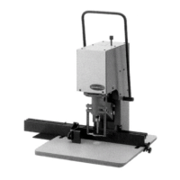
Using Standard Backgauge:
Attach the backgauge assembly to the table and set
both sides to the 6-7/8” position (as shown in fig. 1-3).
Next, position the table so that the back surface of the
backgauge comes in contact with the front of each pull
down shaft (fig. 1-4). Now tighten the front two table-
mounting screws. Then move the backgauge forward
and tighten the rear two screws.
(fig. 1-4)
Pull Down
Shaft
(fig. 1-2)
(fig. 1-5)
Ruler set
to 1-7/8”
Pull Down
Shaft
Backgauge
set to 6”
(fig. 1-3)
Set to 6-7/8”