F.352-KO/EH-3C DRILL/AUG 03
2-2
2.0 OPERATION
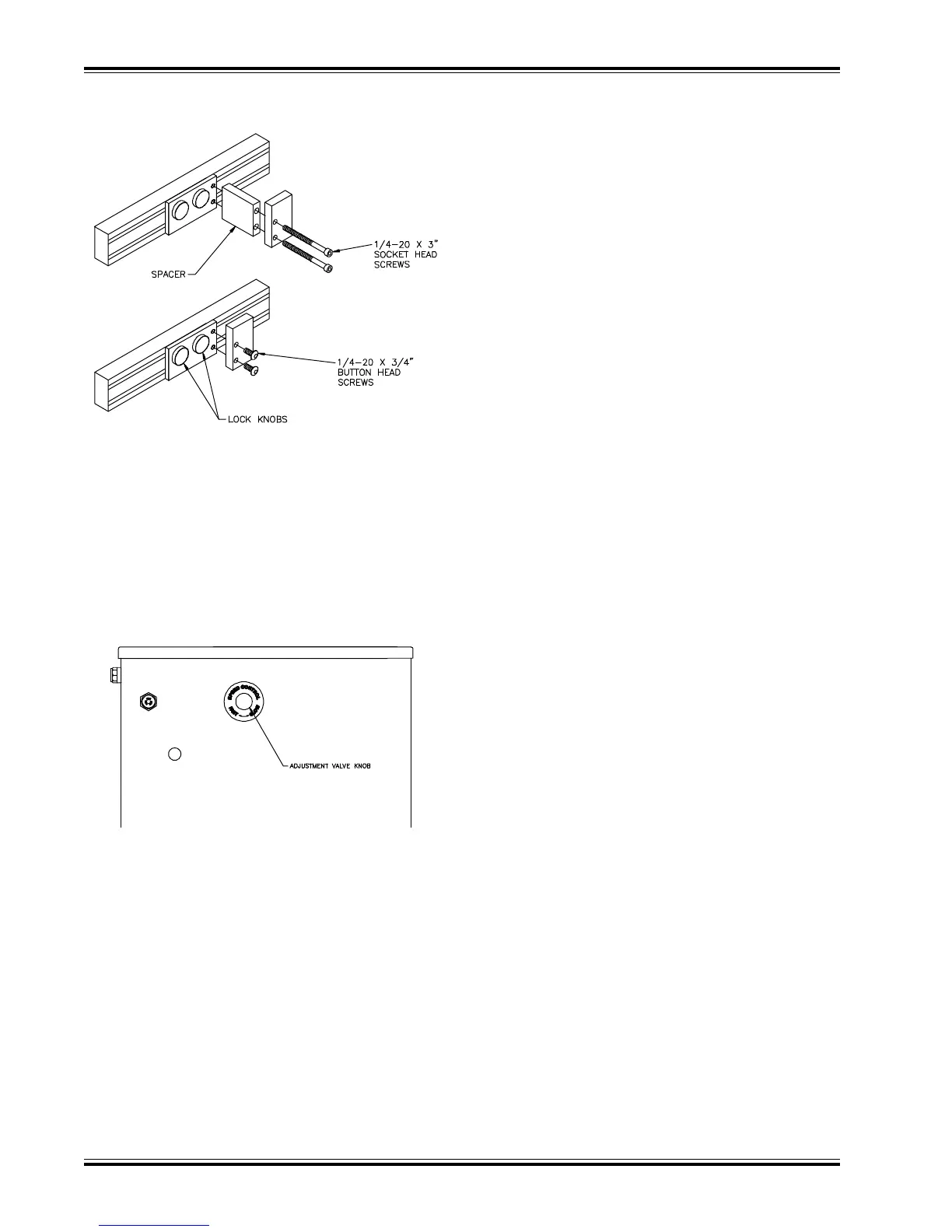
2.6 USING THE SIDE GUIDE
To adjust the position of the side guide, loosen the two
black knobs until the side guide is free to slide side-
ways. Slide the side guide to the desired position and
then tighten the two knobs. For certain hole positions,
it may be necessary to remove the rectangular spacer
from the side guide assembly (fig. 2-1).
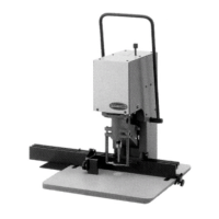
2.7 ADJUSTING THE STROKE SPEED
The hydraulic unit is equipped with an adjustable valve
for regulating the speed on the drill stroke (up and down
travel). Soft stocks such as mimeographs, etc., are
apt to wrinkle at high speeds, and the speed should be
set to a point where the best results are obtained.
This adjustment is made by turning the adjustable valve
(located on the right side of the drilling machine stand)
counterclockwise to reduce speed and clockwise to
increase speed (fig. 2-2)
(fig. 2-1)
(fig. 2-2)
2.8 REMOVING THE CUTTING BLOCKS
Each cutting block is removed by inserting your fin-
gers in the hole provided in the frame (under the table)
and pushing up on the cutting stick knock out. There
are three holes; one on each side of the frame and one
in the front.
2.9 REMOVING DRILLS FROM THE
SPINDLE
Remove the drift hole cover from the spindle to ex-
pose the drift hole. Then, with the flat side down, in-
sert the drill drift into the hole and lift upward. The
upward movement forces the drill down and releases
it from the spindle.