1-3
F.352-KO/EH-3C DRILL/AUG 03
1.0 INSTALLATION & SETUP
Note: Further adjustments may be necessary once the
machine is ready to drill. See Table Position Adjust-
ment (section 4.3.1).
1.3 INSTALLING THE DRILL BLOCKS
AND DRILLS
Place the drill block knock-outs in position (refer to fig.
1-1 if necessary). Now set the three drill blocks place.
Check to see if the blocks are flush with the table. Place
shims under the blocks if necessary.
Insert the tapered head of the hollow drills into the
spindles. Be sure that the drift hole covers are in place
before operating the machine (fig 1-1). The drift hole
covers prevent paper chips from flying out while drilling.
1.4 HYDRAULIC LEVEL CHECK
Check the level of the oil in the hydraulic reservoir. This
check is made by first removing the louvered panel at
the left side of the stand (two screws hold it in place)
and locating the breather cap on the top of the reservoir.
The breather cap has a dip stick attached for checking
the oil. When screwed in (and then removed to check)
there should be approximately an 1/8” (3 mm) of oil on
the stick. Some machines are equipped with a clear
reservoir in which case the oil level can be checked by
visually inspecting the oil level. There is a full level line
marked on the reservoir. Recommended oils are found
in the maintenance section of this manual (section
4.5.1).
1.5 HOOKING UP THE POWER LINE
The EH-3C is factory wired for 208/230 Volt, 1 phase,
50/60 hz. operation. It is the customer’s responsibility
to wire the machine for the rated voltage using a 30
Amp circuit (minimum). The recommended circuit over-
load protection device should be 20 Amps. The recom-
mended wire size for this hookup is #10 gauge.
CAUTION: Always disconnect the
power when cleaning, servicing, or
lubricating your drill, see Lock Out Pro-
cedures, page v.
CAUTION: Always handle drills with
care to avoid severe lacerations. Even
dull drills are sharp enough to cause
lacerations.
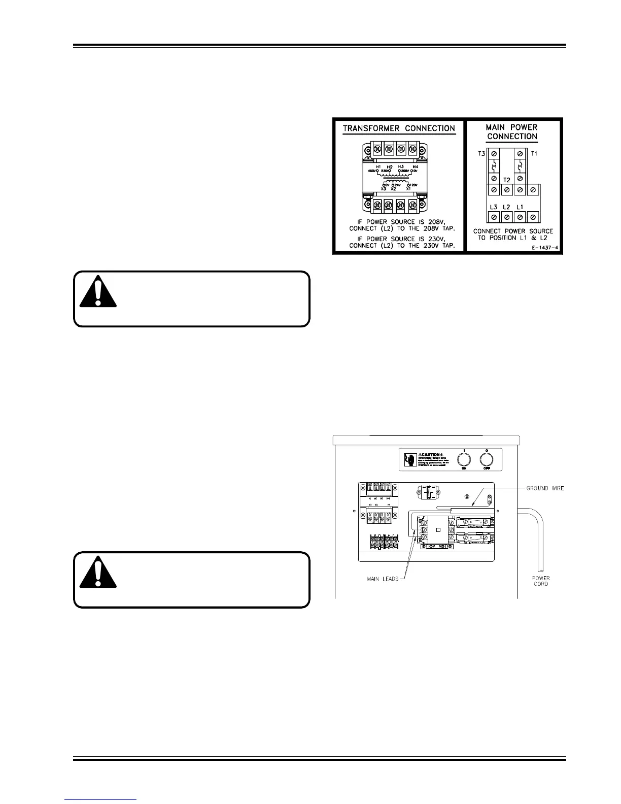
(fig. 1-6)
(fig. 1-7)
IMPORTANT: Select the proper transformer primary
tap 208 or 230 Volts to match the voltage supplied
to the machine (fig. 1-6).
It is also important that the proper line voltage be main-
tained. Failure to do so will result in improper operation
of the machine (see the troubleshooting section of this
manual for specific problems). It may be necessary to
provide a separate branch power line for the machine.
Since the standard machine is intended for a single
phase hookup, simply fasten either wire of the power
cord to either terminal of the starter and the ground wire
to the designated terminal (fig. 1-7).
1.6 INSTALLING THE CHIP CONTAINER
The chip container is installed by slipping it over the two
hooks provided on the rear of the machine.