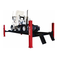
Models 24012 (E, W, EW, XL, LR, AR)
Installation, Operation and Maintenance
File: 24107
4
Rev. 01.09.01
REQUIREMENT COULD RESULT IN PERSONAL INJURY OR PROPERTY
DAMAGE.
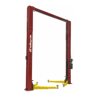
16. Install the bolt end of the cross rail chain into the hole at the top of the off side
posts. Attach the 1" washer and nylon lock nut to the bolt. Hold the chain with a
crescent wrench and tighten the nut to remove most of the slack from the chain.
Repeat for the other cross rail.
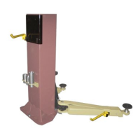
17. Attach the power unit to the front main side post using the 5/16" hardware
provided.
18. Attach the hydraulic hose between the fitting at the rod end of the cylinder and
the fitting just above the power unit tank. Secure the hose to the cylinder with
the tie wraps.
19. Connect the power unit to a dedicated 30 amp electrical branch circuit, using
wiring methods prescribed by local codes. Refer to Fig. 8 for wiring schematic.
20. Using a funnel in the breather cap fitting on the power unit reservoir, fill the
reservoir with 11 quarts of clean petroleum or vegetable based hydraulic oil.
DO NOT OVERFILL THE RESERVOIR. The oil level should be no higher than 2
inches below the mounting flange of the tank. Check by removing the screw just
below the reservoir cap, and filling until oil comes out of the hole. Replace the
screw.
21. Using the power unit, raise the cross rails about 6 inches. Level the cross rails
by adjusting the cross rail chain tension at the top of the off side posts. Use a
level to check the cross rails.
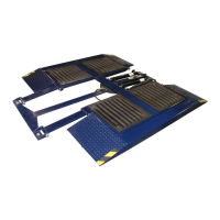
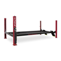
22. Position the runways on the cross rails. Place the runways equal distance from
the center of the cross rails. 36 ½" Between the runways is suggested for model
24012LR, 38 ½" for all other models. Install the “U” bolts provided to each
outside corner of the runways, but DO NOT tighten at this time. If an oil pan or
jacking beam is to be installed, do not install the “U” bolts at the end the jack or
oil pan will be rolled on from until the equipment is installed.
23. Position the off side posts and plumb so that the cross rail chain in the off side
posts hangs straight, the lifting chains in the main side posts hang straight, the
cross rails hang in the center of the post openings and the runways are
positioned correctly on the cross rails.
DO NOT AT THIS TIME DRILL OR INSTALL THE ANCHOR BOLTS FOR
THE OFF SIDE POSTS. THE LIFT MUST BE CYCLED UP AND DOWN AND
CHECKED FOR CORRECT ALIGNMENT BEFORE THE BOLTS ARE
INSTALLED.
 Loading...