7 . ACCESSORIES AND OPTIONS
7.84
Challenger MT500B EU
NOTE: In this section, explanations shall be illustrated
by a disc tiller example.
IMPORTANT: If this implement is hitched to the tractor
lift arms, the linkage must first be set to working posi-
tion and then the TIC menu must be activated (activa-
tion of the TIC menu locks the linkage).
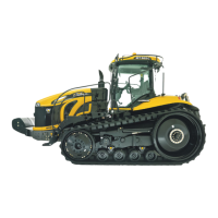
When the window (Fig. 204) is open, press the key «
5
. The
window (Fig. 205) is displayed.
Description:
NOTE: The values that are not in boxes correspond to
instant values.
7.14.0.1 - Calibration
The TIC is operated by the Datatronic which receives infor-
mation from a position sensor located on the rear linkage.
However, for the DUAL CONTROL to operate correctly,
the rear implement position sensor must be calibrated. The
calibration procedure is identical to that described in
paragraph 7.8.3.1. (Calibration).
IMPORTANT: This operation must be performed on
first use, or as soon as work is carried out on the rear
implement position sensor.
NOTE: If a memory is active, the calibration is stored in
this memory.
NOTE: As with the FRONT and REAR DUAL CONTROL,
the calibration can be downloaded into different mem-
ories. The procedure is set out in paragraph 7.8.2.2.
(Downloading the calibration).
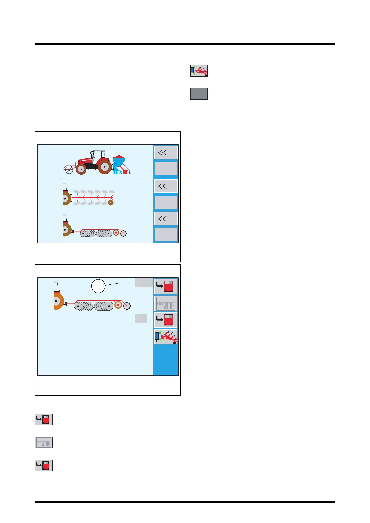
7.14.0.2 - Memorising the disc tiller high and low posi-
tions
For optimum operation, the DATATRONIC must know the
disc tiller high and low positions. For this purpose, the im-
plement hitched to the swinging drawbar must be fitted
with a position sensor connected to the rear of the tractor.
.
Memorising the high position:
• Place the disc tiller in high position (Fig. 206) using a
linkage cylinder spool valve control.
When the spool valve control is actuated, the high position
value varies (68 Fig. 205).
Memorises high implement position
Displays the TIC menu in the Work application
Memorises low implement position
Z3A-817-08-04
1
5
3
?
?
?
Fig. 204
100%
0%
0%
100%
1920
42.0
Z3A-804-08-04-B
Fig. 205
68
1920
42.0
Opens the sensor calibration menu
Greyed boxes: memorised values

 Loading...