28
Installation
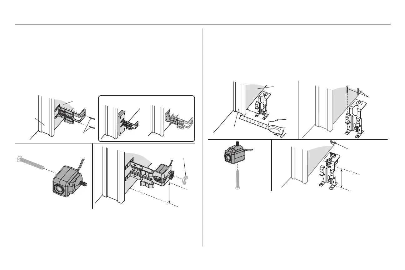
STEP 13 Install the Protector System (continued)
WALL OPTION
Make sure the brackets on each side are clear of the door track and have the same amount of clearance so the
sensors will align correctly. If additional clearance is needed, use extension brackets 041A5281-1 (not
provided) or wood blocks.
1. Attach the sensor bracket against the wall with two lag screws (not provided).
2. Slide the hex screw through the sensor.
3. Attach the sensor to the bracket with the wing nut. Make sure the lens is not obstructed by the
bracket.
Repeat the steps with the other sensor on the opposite side of the garage door. Both lenses must face each
other.
OR
1
Wing Nut
OPTIONAL
2 3
Door track
Inside
garage wall
6" (15 cm)
max.
Not provided
FLOOR OPTION
1. Measure the position of both sensor brackets so they will be the same distance from the wall and
unobstructed.
2. Attach the bracket to the floor with concrete anchors (not provided).
3. Slide the hex screw through the sensor.
4. Attach the sensor to the bracket with the wing nut. Make sure the lens is not obstructed by the
bracket.
Repeat the steps with the other sensor on the opposite side of the garage door. Both lenses must face each
other.
1
3
4
2
Inside
garage wall
Not
provided
Door track
6" (15 cm) max.
Wingnut