For more information, please visit www.devancocanada.com or call toll free at 855-931-3334
Press and hold
STOP...
...then press and
hold CLOSE...
...then press and hold OPEN
until "Er" shows.
CODE SEQUENCE NUMBER
The first number shown is the most recent
code (example: “01”). The display will show
the sequence of codes that occurred starting
with “01” and going up to code “20”.
CODE NUMBER
The second number shown after the code
sequence number is the code itself
(31-99, example” “31”).
A SECOND LATER....
The operator will show the code sequence number followed by the code number:
Diagnostic Codes
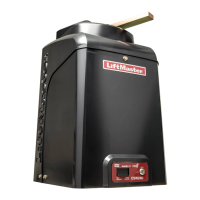
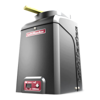
SINGLE PHASE WIRING DIAGRAM
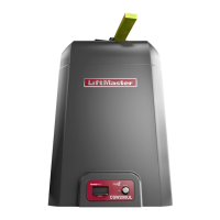
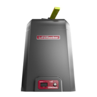
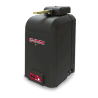
Models SL585U and SL595U
TO VIEW THE CODES:
TRANSFORMER
120V
OUTLET
PWR IN HOT
(BLACK)
SWITCH
(YELLOW)
J15 J14
J13
(BLACK)
(WHITE)
J11 J12
PWR IN
J1
NEUTRAL
(WHITE)
SWITCH
(ORANGE)
J7
COMM
(WHITE)
120V
(BLACK)
208V
(RED)
240V
(ORANGE)
J9 J5 J3
J4J2
J16J6
J10
CURRENT
SENSOR
120V
120V
240V
240V
J8
J17
TRANSFORMER
120V
OUTLET
PWR IN HOT
(BLACK)
SWITCH
(YELLOW)
J15 J14
J13
(BLACK)
(WHITE)
J11 J12
PWR IN
J1
NEUTRAL
(WHITE)
SWITCH
(ORANGE)
J7
COMM
(WHITE)
120V
(BLACK)
208V
(RED)
240V
(ORANGE)
J9 J5 J3
J4J2
J16J6
J10
CURRENT
SENSOR
120V
120V
240V
240V
J8
J17
COMM
LINK
BA
ANTENNA
CURRENT
SENSOR
MOTOR DRIVE
RPM & LIMITS
ALARM
EXP.
BOARD
24 VAC IN
CLASS 2 SUPPLY
24 VAC
500 mA MAX
ID RESET
GND
BIPART
DELAY
2
4
6
8
OPEN
LEFT
OPEN
RIGHT
COMM
LINK
BA
CLASS 2 SUPPLY
24 VAC
500 mA MAX
SHADOW INTERUPT EXIT
SBC
OPN
CLS
STP
COM
EYE
ONLY
EYE/
EDGE
EYE/
EDGE
COM
1
2
3
OPEN
CLOSE
TO MAIN
BOARD
POWER
N.C.
N.O.
COM
C
NO
NC
4
3
2
1
C
NO
NC
RPM & LIMITS
87
654321
9
CURRENT
SENSOR
MOTOR DRIVE
RPM & LIMITS
ALARM
EXP.
BOARD
24 VAC IN
ID RESET
GND
8
7654321
21
4321
4
3
2
1
4321
789654321
21
21
9
10
4321
12
11
10
9
8
7
6
5
4
3
2
1
1
3
10
12
COM
120
240
480
208
HANDING
RESET
BUTTON
CONTROL BOARD
ANTENNA
N.C.
INTERRUPT LOOP
or
PHOTOELECTRIC SENSORS for CLOSE cycle
EDGE SENSOR for CLOSE cycle
SHADOW LOOP
EXIT LOOP
EXIT
OPTIONAL ACCESSORY
WIRING
ACCESSORY POWER
24VAC 2.2 AMPS MAX
FIRE DEPARTMENT
3-BUTTON CONTROL STATION
MAGLOCK
(Optional)
SOLENOID LOCK
(Optional)
OR
Shielded Twisted Pair Cable
(Primary/Secondary link to other
gate operator) Ground the shield of
the cable to the chassis ground of
each operator.
ACCESSORY POWER
24 Vac 500 mA Maximum
(Not Provided)
PHOTOELECTRIC SENSORS
for OPEN cycle
or
EDGE SENSOR
(Not Provided)
Jumper
ALARM
Black
White
White
Orange
Purple
Gray
Green
Blue
Red
Black
White
White
Orange
Red
ACCESSORY POWER OUTLET
Black
Red
Attach to
metal chassis
TRANSFORMER
These switches determine if the corresponding
photoelectric sensor or edge sensor will function
for the OPEN or CLOSE cycle.
PLUG-IN LOOP DETECTOR
Model LOOPDETLM
EXPANSION BOARD
N.C.
SHADOW LOOP
EXIT LOOP
INTERRUPT LOOP
AUXILIARY
RELAY 2
AUXILIARY
RELAY 1
These switches control how the Auxiliary Relays will function.
Jumper
SINGLE BUTTON CONTROL STATION
3-BUTTON CONTROL
STATION
PHOTOELECTRIC SENSORS
PHOTOELECTRIC SENSORS
or EDGE SENSORS
POWER BOARD
Single Phase
POWER BOARD
SINGLE PHASE
Power Wiring
CLOSE
Limit Switch
OPEN
Limit Switch
Limit Switch Wiring
CONTROL BOARD
Black
Blue
Black
Yellow
Black
Green
Red
Black
Yellow
Blue
Blue
Red
HEATER
(Optional Accessory)
AC POWER SWITCH
Normally Open
Common
Normally Closed
Normally Open
Common
Normally Closed
Yellow
Yellow
Yellow
White
Black
Red
Black
White
SWITCH SETTINGS
123
RELAY 1 RELAY 2
OFF
Relay always off
Relay always offOFF OFF
OFF OFF ON Energizes at open limit Energizes at open limit
OFF OFFON Energizes when not at
close limit
Energizes when not at
close limit
OFF ONON Energizes when motor is on Energizes when motor is on
ON OFFOFF
Energizes 3 seconds prior
and during gate motion
Energizes 3 seconds prior
and during gate motion
ON OFFON
Not used Not used
ON ONOFF
Energizes when gate is
tampered with
Energizes when gate is
tampered with
ON ONON LEDs will blink cycle count Not used
RED/GREEN LIGHT FUNCTIONALITY
123
Red light wired to AUX RELAY 1. Green light wired to AUX RELAY 2.
AUX RELAY 1 SWITCHES
OFF
Red light OFF*
OFF OFF
CLOSED
GATE STATE
AUX RELAY 2 SWITCHES
Green light OFF
ON ON ON
OPENING
OPEN
CLOSING
Defined Mid Stop
Undefined Mid
Stop
Timer more than
5 seconds
Timer less than
5 seconds
* For red light ON when gate is closed, set switch 1 on AUX RELAY 1 to ON
Red light ON/FLASH
Red light OFF
Red light ON/FLASH
n/a
Red light ON
Red light OFF
Red light ON/FLASH
Green light OFF
Green light ON
Green light OFF
Green light OFF
n/a
Green light OFF
Green light ON
Yellow
Blue
Yellow
Blue
MOTOR
HARNESS
To configure the motor for
208V, swap the orange and
red wires and plug motor
into the 240V position.
SOLENOID BRAKE
MOTOR
RPM BOARD
RUN 1
RUN 2
THERMAL SWITCH
START
Blue
Yellow
Yellow/Black
Orange
White
Red
Purple
Yellow/Black
Purple
Black
24 VAC
3.15A FUSE
HORSE POWER ID
1/2 HP - Yellow
1 HP - Purple
1 1/2 HP - Blue
PRODUCT ID
SL585U - Blue
SL595U - Black
Yellow
Black
White
Green
Attach to metal
chassis
Attach to metal
chassis
AC POWER SWITCH
Black
White
JUNCTION BOX
HOT
NEUTRAL
GROUND
INCOMING POWER
LiftMaster System
Installed System
Informational
External Entrapment Protection
Inherent Entrapment Protection
CODE COLOR KEY:
• DISCONNECT power BEFORE installing or servicing operator.
• Replace ONLY with fuse of same type and rating.
• To be compliant with UL325 and industry safety guidelines, qualified monitored
external entrapment protection devices such as photoelectric sensors or edge
sensors are required to be installed with this operator at each entrapment zone.
Use ONLY LiftMaster approved entrapment protection devices (refer to the
accessory page of manual).
• See manual regarding maintenance and required safety testing prior to servicing.
MEANING SOLUTION
31
Main control board has
experienced an internal
failure.
Disconnect all power, wait 15 seconds, then reconnect power
(reboot). If issue continues, replace main control board.
35
Max-Run-Time Exceeded
Error
Attempt to run and review for duration and obstructions.
Max-Run-Time can be re-measured by saving one or both of
the limits again.
36
Product ID Error Was the control board just replaced? If so, erase limits, enter
limit setup mode and set limits. If not, disconnect all power,
wait 15 seconds, then reconnect power before changing
product ID harness.
37
Product ID Failure Unplug product ID harness then plug back in. Disconnect all
power, wait 15 seconds, then reconnect power before
replacing product ID harness.
43
Failure or missing EXIT loop Check loop wiring throughout connection. May be a short in
the loop, or an open connection in the loop (LiftMaster Plug-
in Loop Detector only).
44
Failure or missing SHADOW
loop
45
Failure or missing
INTERRUPT loop
46
Wireless edge battery low Replace batteries in wireless edge.
47
Power board fault Relay fault detected in the power board. Replace the power
board.
50
Run-Distance Error Limits are less than 4 feet apart or longer than what was
learned. Check limit positions and proper switch function.
Run-distance can be re-learned by setting the handing again.
53
Brownout occurred AC/DC board supply dipped below allowable level. Review
power supply and wiring. If rebooting, ensure enough time
for discharge of power to force a fresh boot.
54
Wireless Second Operator
Communication Error
Check the second operator for power. If OFF, restore power
and try to run the system. If powered, deactivate the wireless
feature and then re-learn the second operator.
55
System AC Overvoltage Call utility.
56
System AC Undervoltage Check wiring and wire gauge to operator.
57
Limit Error - Stuck Switch Check switch for proper operation. Check harness for shorts.
Replace if defective.
58
Limit Error - Wrong Switch Check motor wiring.
59
Missing Power Board Check harness for shorts. Check for presence of power
board.
60
Minimum number of
monitored entrapment
protection devices (one) not
installed.
Review monitored entrapment protection device connections.
61
CLOSE EYE/INTERRUPT held
more than 3 minutes
Check wired input on main board; check for alignment or
obstruction.
62
CLOSE EDGE held more than
3 minutes
63
OPEN EYE/EDGE held more
than 3 minutes
64
CLOSE EYE/INTERRUPT held
more than 3 minutes
Check wired input on expansion board; check for alignment
or obstruction.
65
CLOSE EYE/EDGE held more
than 3 minutes
66
OPEN EYE/EDGE held more
than 3 minutes
67
Wireless edge triggered more
than 3 minutes
Check wired input for wiring issue or obstruction.
68
Wireless edge loss of
monitoring
Check wireless edge inputs.
69
Wireless edge triggered IF an obstruction occurred, no action required. If an
obstruction did NOT occur, check inputs and wiring.
70
CLOSE EYE/INTERRUPT
triggered, causing reversal,
preventing close, or resetting
TTC
IF an obstruction occurred, no action required. If an
obstruction did NOT occur, check alignment, inputs, and
wiring on main board.
71
CLOSE EDGE triggered,
causing reversal, preventing
close, or canceling TTC
72
OPEN EYE/EDGE triggered,
causing reversal or
preventing opening
73
CLOSE EYE/INTERRUPT
triggered, causing reversal,
preventing close, or resetting
TTC
IF an obstruction occurred, no action required. If an
obstruction did NOT occur, check alignment, inputs, and
wiring on expansion board.
74
CLOSE EYE/EDGE triggered,
causing reversal and
preventing close or canceling
TTC
75
OPEN EYE/EDGE triggered,
causing reversal or
preventing opening
80
Close input (EYE/EDGE)
communication fault from
other operator
Check inputs and communication method between operators,
either wired bus or radio. Ensure operator is powered. May
have to erase the wireless communication and reprogram the
two operators.
81
Open input (EYE/EDGE)
communication fault from
other operator
82
Close input (EYE/EDGE)
communication fault
(expansion board)
Check the connections between the main board and the
expansion board.
83
Open input (EYE/EDGE)
communication fault
(expansion board)
91
Force Reversal Look for obstruction, if no obstruction, check that the
mechanical assembly is engaged and free to move. Refer to
manual for Limit and Force Adjustment, and Obstruction
Test.
93
RPM / STALL Reversal Check for obstruction. If no obstruction, check the operator
cable wiring and that the operator arm is engaged and free to
move. Replace RPM assembly.
95
AC motor no start condition Motor failed to start. Check for an obstructed gate or binding
mechanism. Check start capacitor connections and condition.
99
Normal Operation No action required
TO SCROLL THROUGH THE SAVED CODES:
Press the OPEN button to cycle to the most recent code ("01"). Press the CLOSE button
to cycle to the oldest code (up to “20”).
LiftMaster.com
© 2015, LiftMaster
All Rights Reserved
SINGLE PHASE WIRING DIAGRAM
Models SL585U and SL595U