
R
Randall GillJul 31, 2025
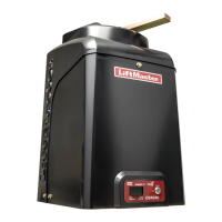
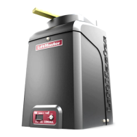
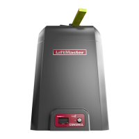
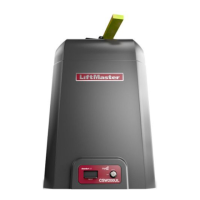
What to do if Chamberlain Gate Opener main control board fails?
- NNicolas CochranJul 31, 2025
If the main control board of your Chamberlain Gate Opener fails, try these steps: First, disconnect all power to the unit. Wait for 15 seconds, and then reconnect the power to reboot the system. If the problem persists after rebooting, the main control board likely needs to be replaced.