EasyManua.ls Logo

Chamberlain Elite CSW-200-UL User Manual

Chamberlain Elite CSW-200-UL
50 pages
To Next Page IconTo Next Page
Page #1 background imageLoading...
Page #1 background image
O W N E R ’ S M A N U A L
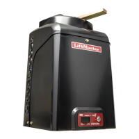
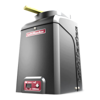
CSW200UL™
VEHICULAR SWING GATE OPERATOR
THE CSW200UL™ IS FOR USE ON VEHICULAR PASSAGE GATES ONLY
AND NOT INTENDED FOR USE ON PEDESTRIAN PASSAGE GATES.
UL325
compliant
UL991
compliant

Questions and Answers:

Chamberlain Elite CSW-200-UL Specifications

General IconGeneral
TypeSwing Gate Opener
Power Supply120V AC
Motor Power1/2 HP
Motor TypeDC
Maximum Gate Weight1000 lbs
Max Gate Length20 ft
Maximum Gate Length20 ft
Remote ControlYes
Number of Remote Controls Included2
Warranty5 Years
Control TypeKeypad, Remote Control
Safety FeaturesObstruction Detection

Summary

Specifications and Warnings

CSW200ULTM Models Overview

Details specifications for single motor, dual motor, and 1 HP models.

UL325 Model Classifications

UL325 Entrapment Protection Requirements

Outlines entrapment protection requirements for UL325 classes.

Safety Installation Information

Suggested Entrapment Protection Device Locations

Non-Contact Sensors (Photo Electric Sensors)

Illustrates placement of photo electric sensors for gate safety.

Contact Sensors (Edge Sensors)

Safety Precautions

Warning Sign Placement

Guidelines for correctly placing warning signs on gate sides.

Installation

Installation Setups

Illustrates single operator and master/second operator installation layouts.

Concrete Pad and Arm Attachment

Standard Installation Layout

Compact Installation Layout

Uphill Driveway Installation (Optional)

Post Mounting Plate Installation (Optional)

Gate Arm Installation

Output Shaft Adjustment

Instructions for adjusting the gate operator's output shaft.

OmniControl™ Board Description

Wiring

Earth Ground Rod Installation

Explains the importance and method of installing an earth ground rod.

110 Vac Power Connection

Linking Master / Second Operators

Partial Master/Individual Control

Describes configuration for partial master/individual gate operator control.

Solenoid/Maglock J3 Connection

Solenoid/Maglock Relay Connection

Factory Installed DC2000™ Connection

DC2000™ Startup

Steps for starting up the DC2000™ backup unit.

System Setup

Configuration options for the DC2000™ system settings.

DC2000™ Device Wiring

Manually Operated DC2000™ Devices

Wiring for manual push buttons and key switches for DC2000™.

Plug-In Loop Detector Wiring

Entrapment Protection Devices

Contact Sensors (Edge Sensor)

Details on installing and using contact edge sensors for safety.

Non-Contact Sensors (24 VDC Photo Electric Sensors)

Adjustments

Set Gate Opening Direction

Instructions for setting the gate's opening direction (left or right).

Limit Switch Adjustment

315 MHZ 24 VDC Radio Receiver Programming

Receiver Configuration

Settings for security mode and output duration.

Receiver Operation

Setting the Timer

Single Operator

Setting the timer for single operator systems.

Adjusting Reversing Sensor(s)

Maintenance and Operation

Important Safety Instructions

Critical safety instructions for gate operator maintenance and operation.

Built-In Reset Switch

Emergency Manual Release

Wiring Diagram • CSW200ULTM and CSW200ULDMTM

Wiring Diagram • DC2000™ FOR SINGLE AND DM

Troubleshooting

Resetting Motor(s)

Procedure for resetting motors when thermal breaker trips.

Repair Parts

How to Order Repair Parts

Installation Checklist

Warranty Policy

Related product manuals