1
For use in all Logic 5.0 commercial door operators.
INSTALLATION
DO NOT connect the power or activate the operator until instructed
to do so.
REMOVE THE EXISTING LOGIC BOARD
1. Disconnect power from the operator.
2. Disconnect all wires from the board:
• Control Wiring Terminal Block
• System Wiring Connector (J3)
• Coaxial antenna
NOTE: Remember the location of all wiring connections for
reinstallation.
3. Remove option boards on slots 1 and/or 2 (if present).
4. Disconnect the yellow Current Sense wire (if present).
5. Remove the logic board from its four mounting posts using
needle nose pliers or a fl athead screwdriver.
LOGIC BOARD (L5)
REPLACEMENT KIT
K001D8395
To avoid SERIOUS personal INJURY or DEATH from
electrocution, Disconnect electrical power to operator BEFORE
proceeding.
INSTALL THE NEW LOGIC BOARD
1. Install the new power board into the operator. Position the
board onto mounting posts pressing fi rmly to ensure posts are
completely through mounting holes.
2. Reconnect all wires:
• Control Wiring Terminal Block
• System Wiring Connector (J3)
• Coaxial antenna
3. Install option boards in slots 1 and/or 2.
4. Set the jumper for motor direction.
5. Make sure the electrical box is clear of all debris and tools.
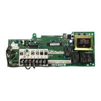
Control wiring
terminal block
Slots for option boards
Coaxial antenna
connecter
System wiring
connector (J3)
Motor direction
jumper
Current Sense
(3 Phase Only)
WARNING: This product can expose you to chemicals
including lead, which are known to the State of California to
cause cancer or birth defects or other reproductive harm.
For more information go to www.P65Warnings.ca.gov