
M
Michelle JeffersonAug 17, 2025
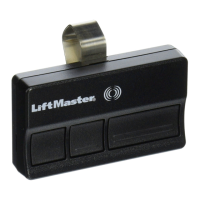
What to do if my Chamberlain LiftMaster MJ5011U Garage Door Opener remote gives no response?
- BBrian HuertaAug 17, 2025
If your Chamberlain Garage Door Opener remote is not responding: * **Remote control is not programmed:** See PROGRAMMING REMOTE CONTROLS section. * **Remote control not compatible:** Obtain qualified LiftMaster remote control device. * **Low battery:** Replace the battery.